Self powered illuminated bi-directional street sign

a self-powered, street sign technology, applied in the direction of instruments, boards, transportation and packaging, etc., can solve the problems of not being illuminated, their use at night very limited, and the luxury of corner intersection street signs mounted on posts

Inactive Publication Date: 2015-10-22
SENONAL FERHAT +1
View PDF6 Cites 3 Cited by
  • Summary
  • Abstract
  • Description
  • Claims
  • Application Information

AI Technical Summary

Benefits of technology

[0016]It is an object of the present invention to provide a self powered illuminated bi-directional street sign that does not require any outside energy source for illumination.
[0018]It is yet another object of the present invention to provide a self powered illuminated bi-directional street sign that uses the same light source to light both sides of a dual sided housing while preventing visual interference between the dual sides.
[0019]It is another object of the present invention to provide a self powered illuminated bi-directional street sign that does not require any outside energy source for illumination that utilizes efficient illumination devices comprising LED lighting to minimize electric power consumption and, thereby, minimize the number of batteries and the size of the solar array required to charge the batteries.
[0020]It is yet another object of the present invention to provide a self powered illuminated bi-directional street sign that does not require any outside energy source for illumination wherein both sides of a bi-directional street sign housing are backlit by the same light source.
[0022]It is yet another object of the present invention to provide a self powered illuminated bi-directional street sign that does not require any outside energy source for illumination wherein a solar array is mounted to the top of the post on which the street signs are mounted to provide a protective canopy as well as being optimally placed to receive sunlight.
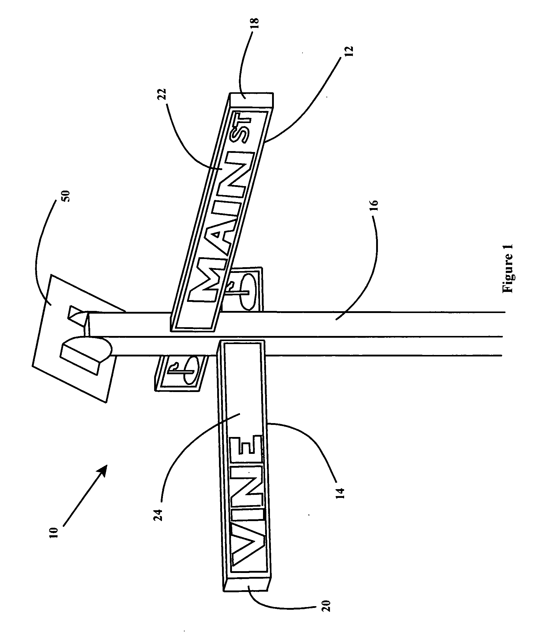
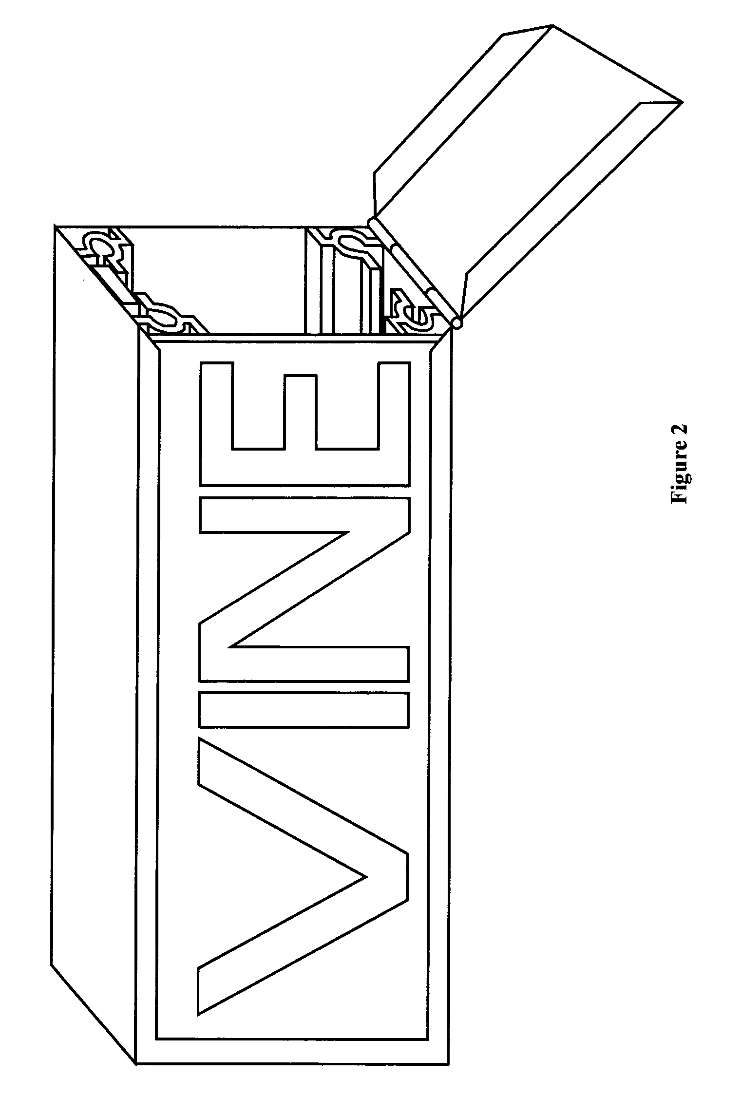
[0025]The street sign assembly in the most preferred embodiment comprises two housings secured to said post. These two housings each comprise two opposed illuminated faces and are structurally resilient to weather, wind and vandalism. In the most preferred embodiment of the present invention, the means for illuminating comprises internal illumination means positioned within each of the two housings. To avoid visual interference the two housings have means for preventing visual interference between their opposed faces.

Problems solved by technology

Street signs have long had a major flaw in that they are not illuminated, making their use at night very limited.
A driver attempting to follow directions by following or checking the street he is on will either find it impossible or will have such difficulty reading unlit street signs that he will be forced to get very close to the street sign and, in many instances, exit the vehicle, to be able to read the street sign.
That is, while street signs mounted high above the street of major roadways and thoroughfares are often hung from the same supporting structure as traffic lights and lighted by spotlights that are powered by the same electrical supply that is already available and present for the traffic lights, that luxury is not available for the corner intersection type street signs mounted on posts.
For every community in the United States that has un-illuminated corner intersection street signs, the cost to run an electric service feed to the signs would be enormous, particularly if the electric service was run underground throughout the subdivision.
It has long been the bane of the traveler trying to find a location at night that street signs on small sidestreets and in suburban neighborhoods are not lit, making the already difficult task of following directions given by someone else even more frustrating.
U.S. Pat. Nos. 6,131,321 and 6,994,448 also disclose devices and systems for illuminating house numbers to make them more usable for the traveler after dark, but each of those devices and systems have disadvantages when considering their possible application to bi-directional street signs mounted on posts, generally positioned on corners where two streets intersect.
The street name signs are generally elevated, 7 to 10 feet above the ground, so any spotlight illumination of the street signs from ground level is very difficult and impractical.
The solutions for illuminating house numbers, and other signage similar to the street signs with which we are here concerned, all have disadvantages when applied to the traditional pole mounted corner intersection street signs.
Any solution that uses alternating current electricity has the major disadvantage of the cost of running power lines to every street corner.
It is impractical to expect electric service to be available near a corner intersection where the post mounted street signs are found.
As mentioned above, the cost to run electric service to illuminate street signs is prohibitive, whether it would be run overhead or underground, and it also would create a new recurring utility expense if electricity is consumed to light the street signs.
However, even those prior art solutions that use solar energy to supply a power storage device such as a rechargeable battery are disadvantageous because of the quantity of illumination required.
If the solar panel is mounted near or on the light structure or pole, the size and weight of the solar panel may become prohibitive.
In addition, any system that is completely reliant upon solar energy to provide the necessary electrical energy to keep batteries charged will suffer from time to time when sunlight is not intense or plentiful enough.
Heretofore the problem of providing a backlit street sign, with translucent panels, which is also adequately strong to withstand predictable hanging from the sign by teenagers and vandals, has not been addressed.

Method used


Image

  • Self powered illuminated bi-directional street sign
  • Self powered illuminated bi-directional street sign
  • Self powered illuminated bi-directional street sign

Examples


Embodiment Construction

[0046]As a preliminary matter, it will readily be understood by one having ordinary skill in the relevant art (“Ordinary Artisan”) that the present invention has broad utility and application. Furthermore, any embodiment discussed and identified as being “preferred” is considered to be part of a best mode contemplated for carrying out the present invention. Other embodiments also may be discussed for additional illustrative purposes in providing a full and enabling disclosure of the present invention. Moreover, many embodiments, such as adaptations, variations, modifications, and equivalent arrangements, will be implicitly disclosed by the embodiments described herein and fall within the scope of the present invention.

[0047]Accordingly, while the present invention is described herein in detail in relation to one or more embodiments, it is to be understood that this disclosure is illustrative and exemplary of the present invention and is made merely for the purpose of providing a ful...


PUM


Abstract

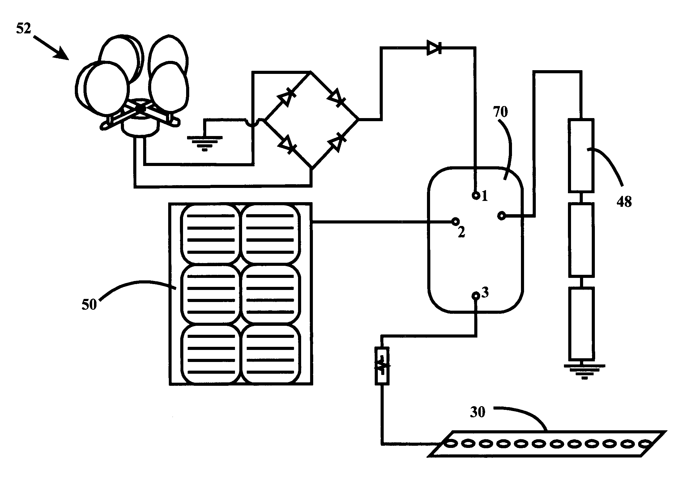
A street sign assembly is provided wherein the panels are illuminated. Two street signs, substantially perpendicularly to one another mounted on a pole near an intersection of two streets, are backlit on both sides to make them visible readable at night. Low power consumption light emitting diodes (LEDs) are used to illuminate the signs and are mounted internal to the sign housing such that the street name is backlit from within the housing, making it more readable from a distance at night. The LEDs are mounted between the two opposed faces of a housing so that their light is used to illuminate both faces. Translucent opposed frosted plates are positioned within the housing to reflect the LED lights and to prevent the mirror images on the two opposed faces from being visible from the other side. The power for the LEDs is provided by rechargeable DC batteries. A solar panel and a DC generator coupled to a wind turbine are installed on the post and are wired to provide charge current to the DC batteries. An electrical charge circuit is provided to control the selection of the charge current and the connection of the battery pack to drive the load.

Description

FIELD OF THE INVENTION[0001]The present invention relates to a bi-directional illuminated street sign assembly that is self powered. The present invention particularly relates to an illuminated street sign that uses solar or wind power to provide the energy necessary for illumination.BACKGROUND OF THE INVENTION[0002]Street signs bearing the name of the road, street, avenue or thoroughfare have long been the necessary aid of travelers seeking a destination with which they are unfamiliar. Even in the age of online navigation tools, signs denoting the names of streets are a necessary resource for people and things to get where they are going, particularly for anyone giving, receiving or following directions to a destination.[0003]Street signs have long had a major flaw in that they are not illuminated, making their use at night very limited. A driver attempting to follow directions by following or checking the street he is on will either find it impossible or will have such difficulty ...

Claims


Application Information

Patent Timeline
Patent Type & Authority Applications(United States)
IPC IPC(8): G09F13/04H02J7/00H02J7/35G09F13/22G09F13/06
CPCG09F13/0413G09F13/22H02J7/007H02J7/35H02J7/0052G09F13/06G09F15/0037G09F15/005H02J1/10H02J7/0042H02J7/34Y02E10/76
Inventor SENONAL, FERHATCOATES, ROBERT BROCK
Owner SENONAL FERHAT
Why Eureka
Try Eureka