Chassis for installing power transmission line image monitoring terminal and installation method

A technology for image monitoring and power transmission lines, applied to electrical components, circuit devices, closed-circuit television systems, etc., can solve the problems of unsafe monitoring terminal protection, inconvenient installation, etc., to avoid visual interference, improve reliability, and avoid heat generation damage effect

Active Publication Date: 2020-06-23
CHONGQING UNIV
View PDF6 Cites 0 Cited by
  • Summary
  • Abstract
  • Description
  • Claims
  • Application Information

AI Technical Summary

Problems solved by technology

[0003] Aiming at the deficiencies of the above-mentioned prior art, the present invention provides a chassis for installing a transmission line image monitoring terminal, which solves the technical problems of inconvenient installation, unsafety and poor protection of the monitoring terminal in the prior art

Method used


Image

  • Chassis for installing power transmission line image monitoring terminal and installation method
  • Chassis for installing power transmission line image monitoring terminal and installation method

Examples


Embodiment Construction

[0030] The present invention will be further described in detail below in conjunction with the accompanying drawings and preferred embodiments.

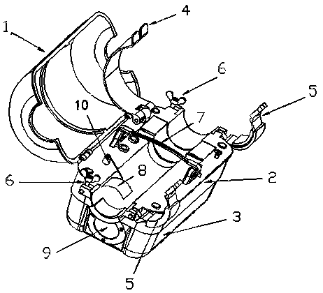
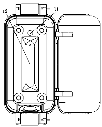
[0031] like figure 1 As shown, a chassis for installing a power transmission line image monitoring terminal includes an upper cover 1, an inner cover 2 and a bottom box 3; Transitional connection; the adjacent sides of the bottom box 3 are also transitionally connected by arc surfaces; the upper cover 1 is made of insulating material, the inner cover 2 and the bottom box 3 are made of metal materials; the bottom of the inner cover 2 and the bottom box 3. The opening at the upper end is sealed and connected, so that a sealed compartment for installing the image monitoring terminal is formed in the bottom box 3; the sealed compartment is filled with inert gas; one side of the bottom box 3 is sealed with a seal for revealing the image monitoring terminal. The lens 9 of the camera; the inner cover 2 is provided with an equipotential con...


PUM


Abstract

The invention discloses a cabinet used for installing a power transmission line image monitoring terminal. The cabinet includes an upper cover, an inner cover, and a bottom box, the upper cover is made of an insulating material, and the inner cover and the bottom box are made of metal materials; the bottom of the inner cover is sealingly connected with an opening of the upper end of the bottom box, so that a sealed chamber for mounting the image monitoring terminal is formed in the bottom box; the inner cover is provided with an equipotential contact sheet and at least one main conducting linefastener used for locking the cabinet on a power transmission conducting line; one end of the equipotential contact sheet is embedded in the inner cover and protrudes into the sealed chamber, and theother end extends toward the power transmission conducting line and can be in contact with the power transmission conducting line, so that the equipotential contact sheet can be used for connecting the power transmission conducting line with a ground wire of the image monitoring terminal, and so, the image monitoring terminal is equipotential with the power transmission conducting line; and a connection between the equipotential contact sheet and the inner cover is sealed. The invention also discloses an installation method of the power transmission line image monitoring terminal. The cabinetand the installation method solve the technical problems that installation is inconvenient and unsafe, and protection of monitoring terminals is poor in the prior art.

Description

technical field [0001] The invention relates to the technical field of on-line monitoring of power transmission lines, in particular to a chassis for installing a power transmission line image monitoring terminal, and also relates to a method for installing a power transmission line image monitoring terminal. Background technique [0002] With the rapid development of electric power construction, the scale of the power grid continues to expand, and there are more and more work on power grid construction and equipment maintenance under complex terrain conditions. An important part of. In order to ensure the safe and stable operation of the power system, it is indispensable to install some online monitoring devices for high-voltage transmission lines. The installation and fixing structure of the existing transmission line online monitoring device is complicated, and the installer cannot fully understand it in a short time, and it is difficult to achieve the expected fixing ef...

Claims


Application Information

Patent Timeline
Patent Type & Authority Patents(China)
IPC IPC(8): H02J13/00H04N7/18
CPCH02J13/00H04N7/18
Inventor 熊小伏
Owner CHONGQING UNIV
Why Eureka
Try Eureka