Non-contact power transmitting and receiving system

a technology of non-contact power and transmission system, applied in the direction of transformers, inductances, sustainable buildings, etc., can solve the problems of reducing transmission efficiency, increasing installation space, increasing cost, etc., and achieve the effect of suppressing the size increase of the system, improving power transmission efficiency, and cost increas

Active Publication Date: 2015-10-22
TOYOTA JIDOSHA KK
View PDF3 Cites 30 Cited by
  • Summary
  • Abstract
  • Description
  • Claims
  • Application Information

AI Technical Summary

Benefits of technology

[0009]The present invention was made to solve the above-described problems, and has an object to provide a non-contact power transmitting and receiving system capable of improving efficiency of power transfer in correspondence with variable factors in transmission efficiency, while suppressing size increase of the system and cost increase.

Problems solved by technology

As shown in Japanese Patent Laying-Open No. 2002-272134, however, when the frequency of the inverter on the power transmitting side is changed, the inverter frequency disadvantageously deviates from set frequency (resonance frequency) of a resonant circuit or a filter circuit to degrade frequency characteristics of a power transmission path, resulting in reduced transmission efficiency.
When providing an additional circuit for adjusting capacitor capacitance on a power transmission path as described in Japanese Patent Laying-Open No. 2012-130173, the system will be increased in size because of the addition of the circuit, resulting in increased installation space and increased cost.

Method used


Image

  • Non-contact power transmitting and receiving system
  • Non-contact power transmitting and receiving system
  • Non-contact power transmitting and receiving system

Examples


first embodiment

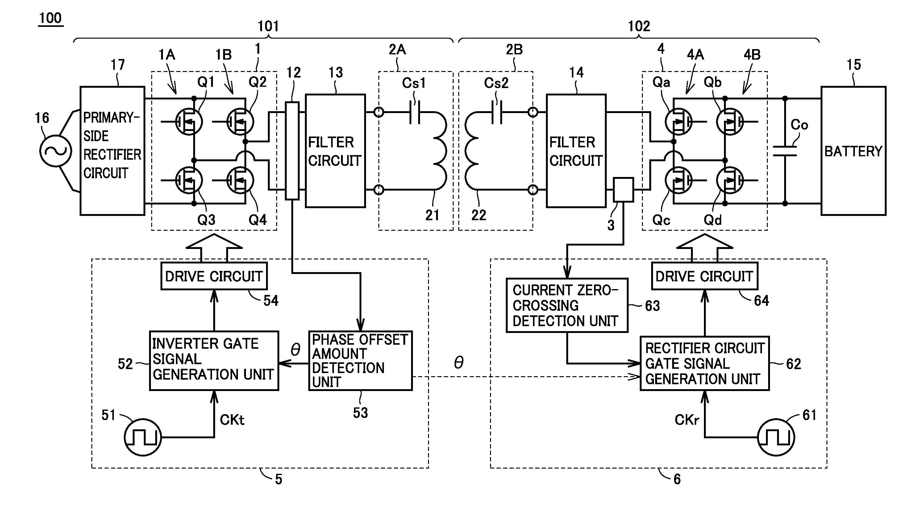
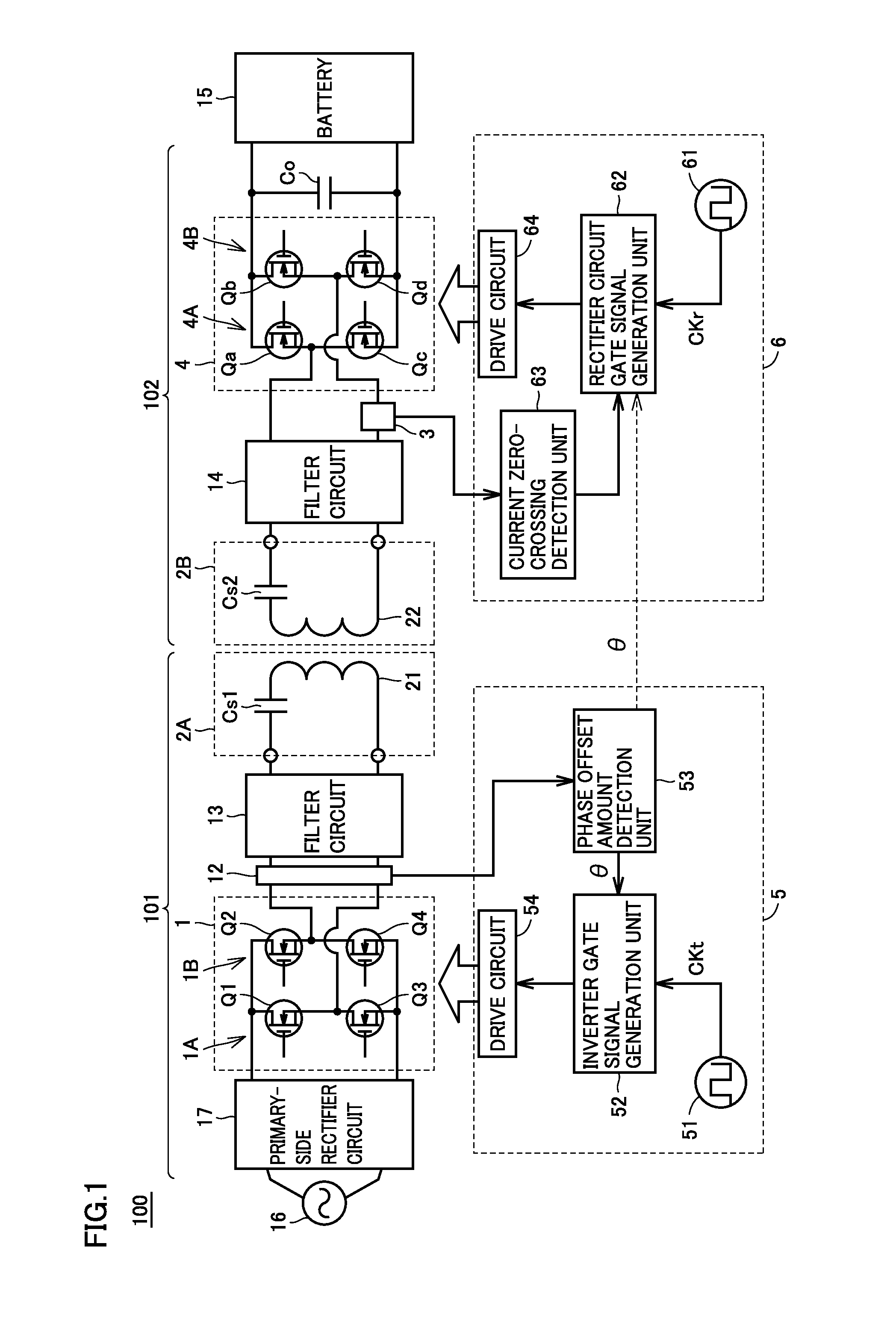
[0035]FIG. 1 is an overall configuration diagram of a non-contact power transmitting and receiving system of a first embodiment. Referring to FIG. 1, a non-contact power transmitting and receiving system 100 includes a power transmitting apparatus 101 and a power receiving apparatus 102.

[0036]Power transmitting apparatus 101 includes a high-frequency inverter 1, a voltage-current sensor 12 detecting an output voltage and an output current of high-frequency inverter 1, a filter circuit 13, a power transmission unit 2A, and a power transmitting-side controller 5. High-frequency inverter 1 includes arms 1A and 1B connected in parallel to each other across a positive electrode power line and a negative electrode power line supplied with a DC voltage from a DC power supply (a primary-side rectifier circuit 17) on the power transmitting side. Arm 1A includes switching elements Q1 and Q3 connected in series. Arm 1B includes switching elements Q2 and Q4 connected in series.

[0037]Power recei...

second embodiment

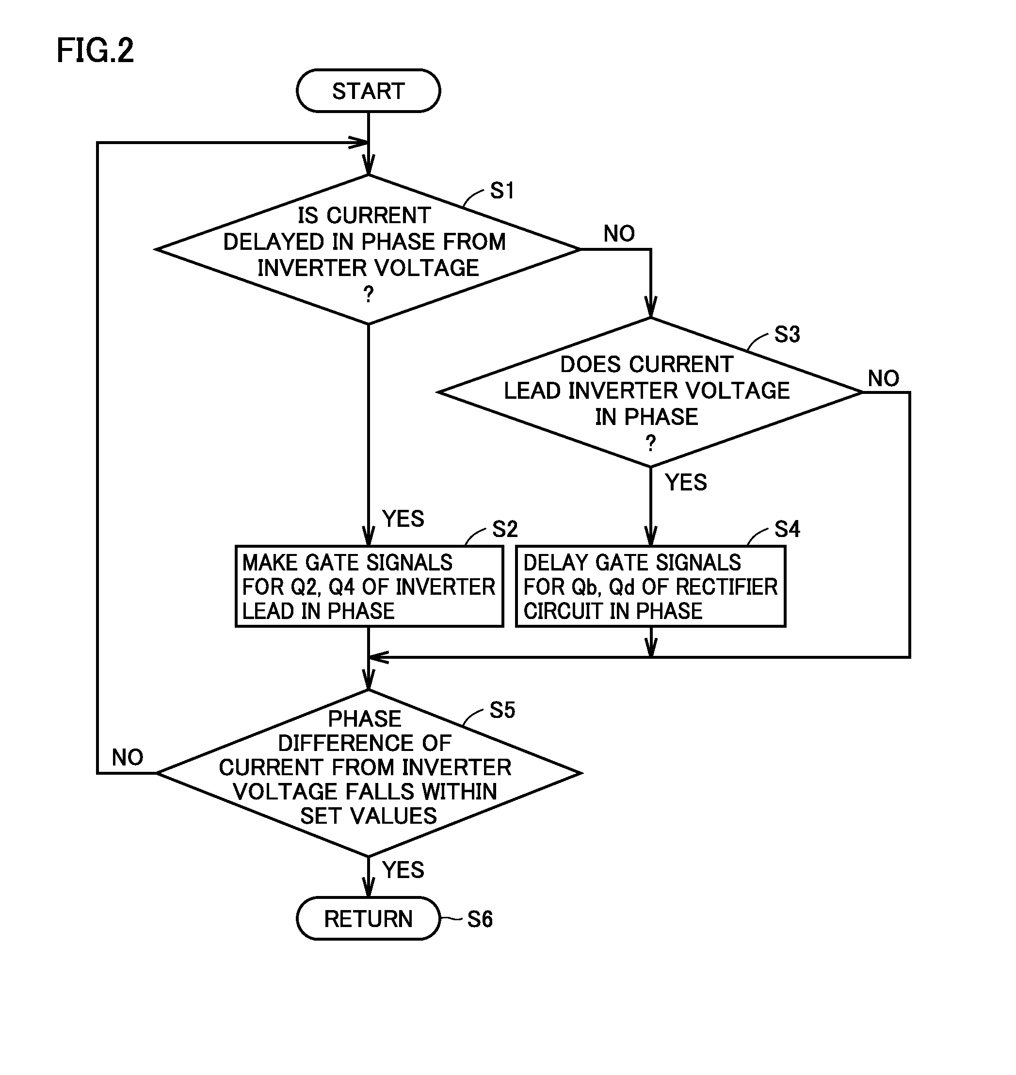
[0080]The first embodiment shows the example of shifting the phase of switching of the inverter or switching of the rectifier circuit in accordance with the phase difference between the inverter current and the inverter voltage. In the second embodiment, an example of shifting the phase of the rectifier circuit further taking charging power and a receiving-terminal voltage-current ratio into consideration, and correcting the phase shift amount in accordance with the phase difference between the inverter current and the inverter voltage will be described.

[0081]FIG. 9 is an overall configuration diagram of a non-contact power transmitting and receiving system of the second embodiment.

[0082]In addition to the configuration of non-contact power transmitting and receiving system 100 shown in FIG. 1, a non-contact power transmitting and receiving system 200 shown in FIG. 9 further includes a receiving terminal voltage detection unit 7 and a battery current detection unit 8. Power receivin...


PUM


Abstract

A non-contact power transmitting and receiving system includes an inverter configured to generate a high-frequency voltage, a voltage-current sensor configured to detect a phase difference between an output voltage and an output current of the inverter, a power transmission coil connected to the inverter, a power reception coil configured to receive electric power from the power transmission coil in a contactless manner, a rectifier circuit connected to the power reception coil, and a control unit configured to control the inverter and the rectifier circuit. The inverter includes arms. The rectifier circuit includes arms. The control unit adjusts at least one of switching timing of any arm of the inverter and switching timing of any arm of the rectifier circuit, in accordance with the phase difference detected by the voltage-current sensor.

Description

[0001]This nonprovisional application is based on Japanese Patent Application No. 2014-088097 filed on Apr. 22, 2014 with the Japan Patent Office, the entire contents of which are hereby incorporated by reference.BACKGROUND OF THE INVENTION[0002]1. Field of the Invention[0003]The present invention relates to a non-contact power transmitting and receiving system.[0004]2. Description of the Background Art[0005]A non-contact power transmitting and receiving system which supplies electric power to a load in a contactless manner is applied for charging a portable electronic apparatus, an electric vehicle and the like. In the non-contact power transmitting and receiving system, electric power is transmitted through a high-frequency power supply, a power transmission unit, a power reception unit, a rectification unit, and a load in the order presented.[0006]In the non-contact power transmitting and receiving system, variable factors in transmission efficiency, such as variations in an equi...

Claims


Application Information

Patent Timeline
Patent Type & Authority Applications(United States)
IPC IPC(8): H02J5/00
CPCH02J5/005H02J50/12H02M3/33576H02M3/3378H02J7/02H02J2207/20Y02B40/00H02M1/0003H02M1/0085
Inventor HAYASHI, YUJIICHIKAWA, SHINJI
Owner TOYOTA JIDOSHA KK
Why Eureka
Try Eureka