Prosthesis member of a joint prosthesis for a thumb joint and joint prosthesis

US20150305788A1Inactive Publication Date: 2015-10-29SWEMAC INNOVATION

Image

  • Prosthesis member of a joint prosthesis for a thumb joint and joint prosthesis
  • Prosthesis member of a joint prosthesis for a thumb joint and joint prosthesis
  • Prosthesis member of a joint prosthesis for a thumb joint and joint prosthesis

Examples


Embodiment Construction

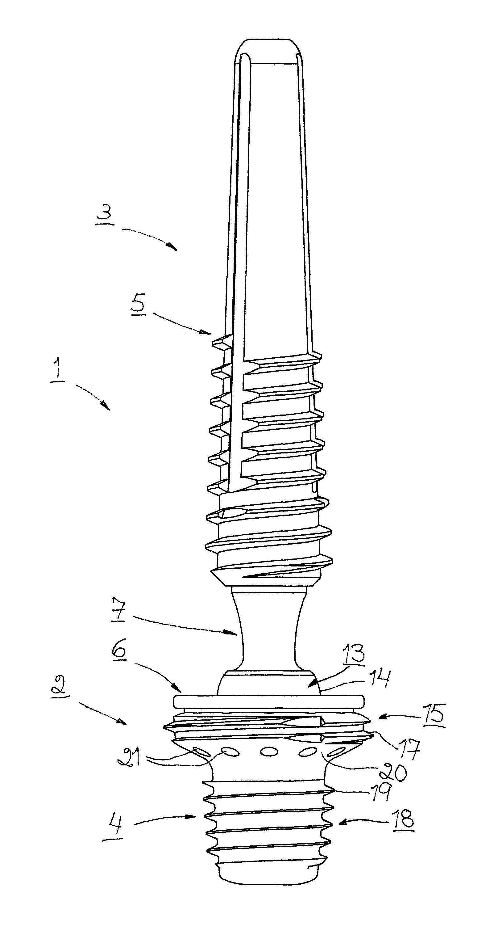
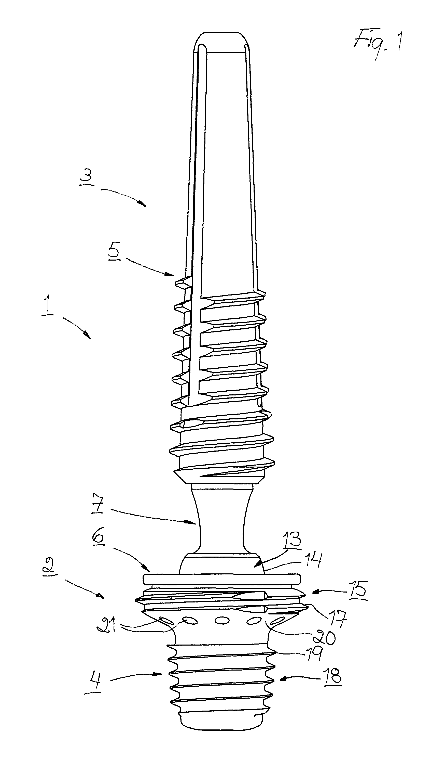
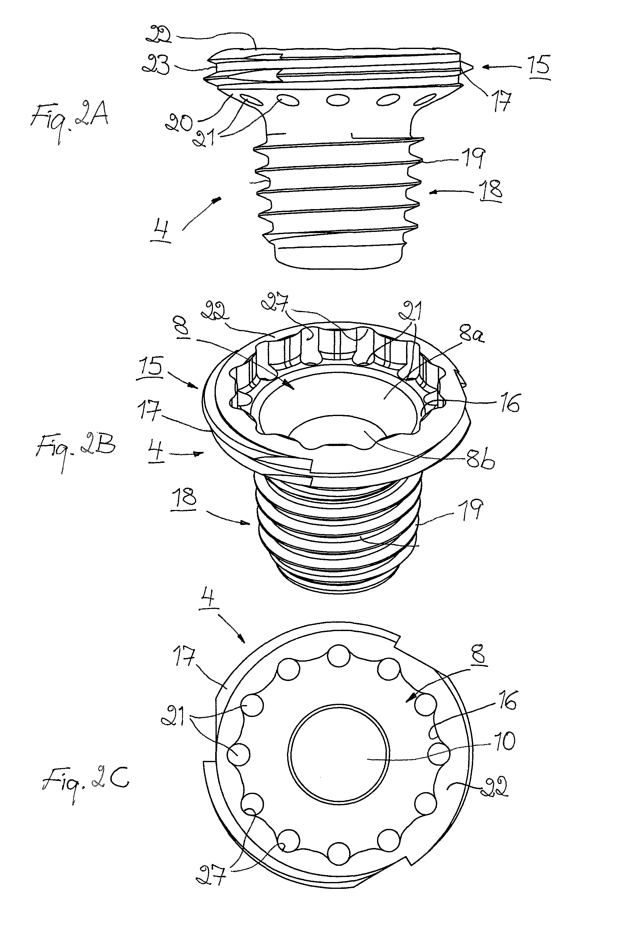
[0021]In drawing FIGS. 1 and 6 there is illustrated a first and second preferred embodiment respectively, of a thumb joint prosthesis 1. The thumb joint prosthesis 1 comprises a first prosthesis member 2 and a second prosthesis member 3. The first prosthesis member 2 comprises a first screw-like part 4 which is adapted for being attached by screwing into the trapezium T at the thumb joint and the second prosthesis member 3 comprises a second screw-like part 5 which is adapted for being attached by screwing into the first metacarpal bone (not illustrated) at the thumb joint. The screw-like parts 4, 5 are for this purpose configured with threads which entirely or partly extend in the longitudinal direction thereof. The first prosthesis member 2 also comprises an articulating socket element 6 and the second prosthesis member 3 comprises an articulating ball element 7. The first and second screw-like parts 4, 5 respectively, are in the illustrated embodiments provided with an attachment...


PUM


Abstract

A prosthesis member of a joint prosthesis for a thumb joint comprises a screw-like part (4) and an articulating socket element (6) with a mounting pin (9) which is insertable into a hole (8) in the screw-like part for attaching the articulating socket element thereto. The screw-like part (4) of the prosthesis member (2) is configured with a first fixing portion (15) which is provided with a first external thread (17) for attachment by screwing and fastening of said prosthesis member to the hard outer part (T1) of the trapezium (T), and a second fixing portion (18) having a less diameter than the diameter of the first fixing portion and being provided with a second external thread (19) which is configured to permit attachment by screwing and fastening of said prosthesis member to the soft inner part (T2) of the trapezium. The first fixing portion (15) is provided with a surface (20) which connects the threads (17, 19) on said fixing portions (15, 18) to each other and which converges substantially arcuate towards the second fixing portion (18). Hereby, optimum fixation of the prosthesis member (2) in the trapezium (T) is achieved.

Description

TECHNICAL FIELD[0001]The present invention relates to a prosthesis member of a joint prosthesis for a thumb joint, wherein the prosthesis member comprises a screw-like part which is adapted for being attached by screwing into the trapezium at the thumb joint and an articulating socket element, and wherein the articulating socket element has a mounting pin which is insertable into a hole in the screw-like part for attaching the articulating socket element thereto. The present invention also relates to a joint prosthesis for a thumb joint, wherein the joint prosthesis comprises a prosthesis member as defined above and a prosthesis member comprising a screw-like part which is adapted for being attached by screwing into the first metacarpal bone at the thumb joint and an articulating ball element.BACKGROUND OF THE INVENTION[0002]The joint prosthesis at which the prosthesis member according to the invention is adapted for use at first hand, comprises two prosthesis members of which one i...

Claims


Application Information

Patent Timeline
29 Oct 2015
Publication
US20150305788A1
IPC
A61B17/86
CPC
A61B17/8685; A61F2/4241; A61F2002/30331; A61F2002/305; A61F2002/30649; A61F2002/3085; A61F2002/4258
Inventors
HANSSON, HENRIK; OSTER, LARS