Screw driving device for recognizing screwing accessories in the coaxial position

a technology of coaxial position and screw drive, which is applied in the direction of screwdrivers, wrenches, spanners, etc., can solve the problems of relative difficulty in reaching, loss of time, and risk of error, and achieve the disadvantage of being fairly impractical to us

Inactive Publication Date: 2015-10-29
ETAB GEORRENAULT
View PDF6 Cites 6 Cited by
  • Summary
  • Abstract
  • Description
  • Claims
  • Application Information

AI Technical Summary

Benefits of technology

[0046]It is thus possible to fixedly attach different screw driving accessories to the s

Problems solved by technology

In addition, certain screws can be situated in congested surroundings and therefore be relatively difficult to reach.
These changes of screw driving accessories and selection of screw driving strategies leads to loss of time and a risk of error.
These cases however have the drawback of being fairly impractical for use because of their substantial volume and the cable that connects them to the screwdriver especially in narrow and/or congested work spaces.
This technical solution does not have the drawbacks of sockets cases in terms of practicality of use.
The means for fixedly attaching the screw driving accessories

Method used


Image

  • Screw driving device for recognizing screwing accessories in the coaxial position
  • Screw driving device for recognizing screwing accessories in the coaxial position
  • Screw driving device for recognizing screwing accessories in the coaxial position

Examples


Embodiment Construction

[0063]6.1. Architecture

[0064]6.1.1. Screwdriver

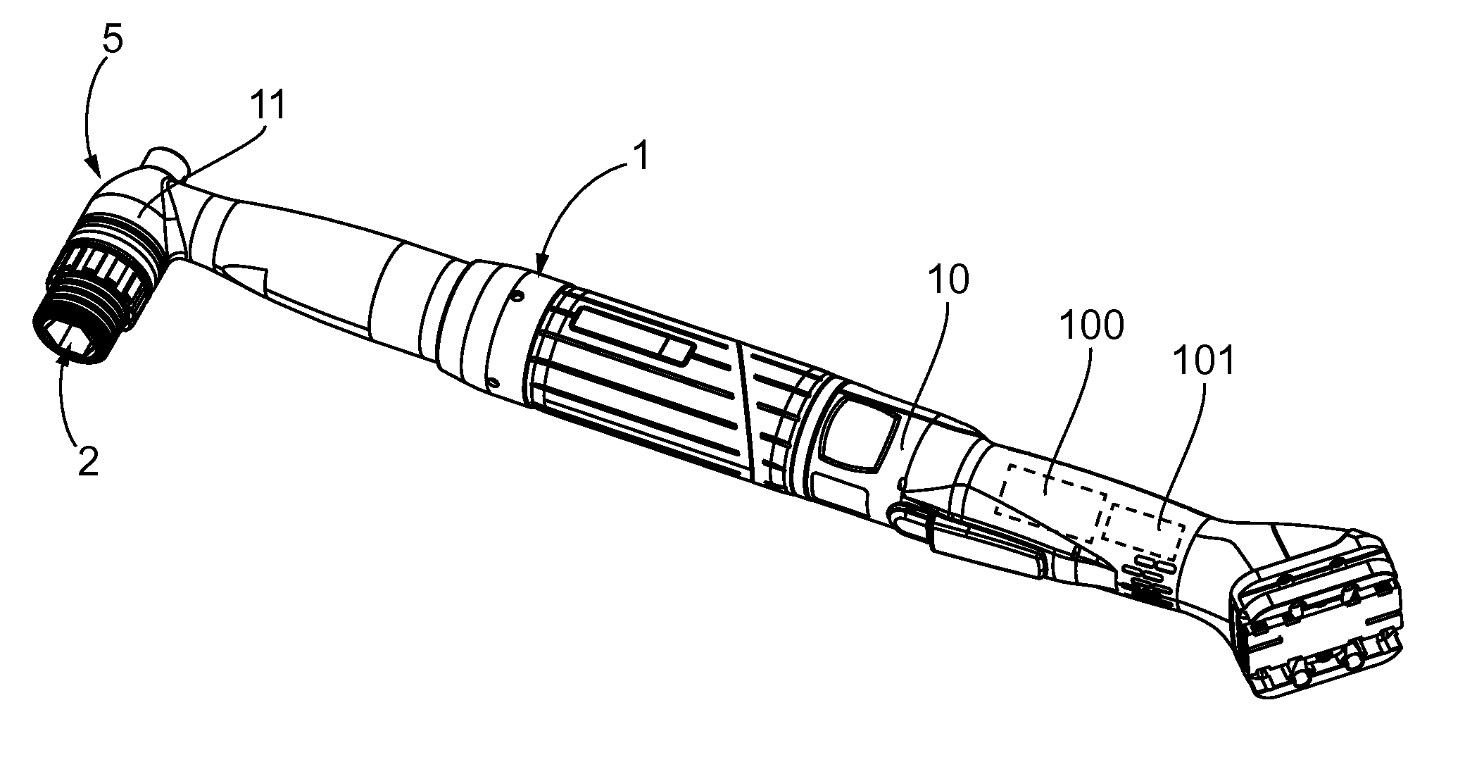
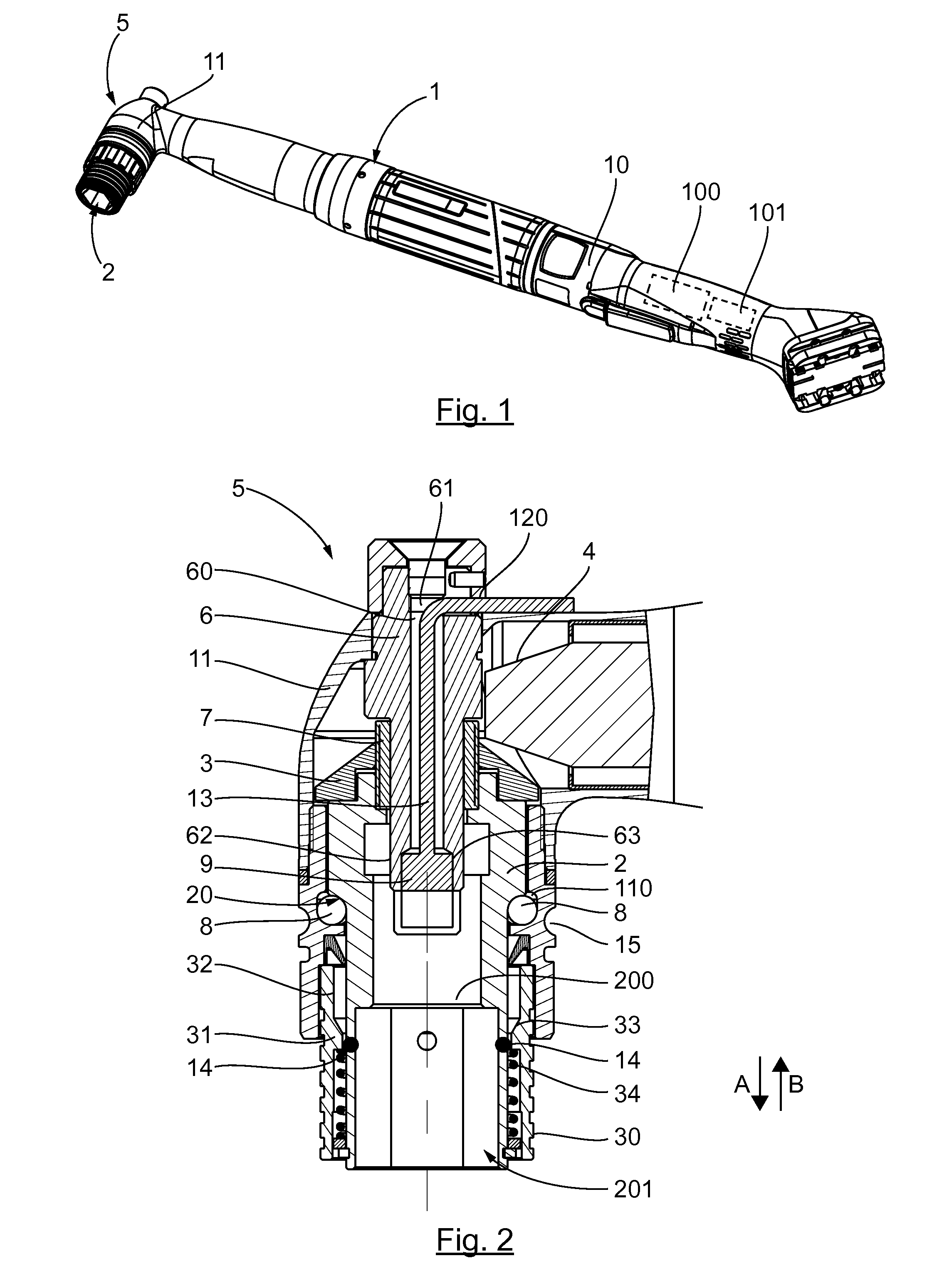
[0065]Referring to FIGS. 1 and 2, we present an example of an embodiment of a screw driving device according to an exemplary embodiment.

[0066]As shown in these figures, such a screw driving device conventionally comprises a body 1. This body 1 comprises a first portion 10 which houses a motor. In this embodiment, this is an electric motor 100. The body 1 also has a second portion 11 which houses an output shaft 2. As shall be explained in greater detail here below, this shaft 2 is provided to cooperate with a screw driving accessory so as to drive it in rotation.

[0067]The body 1 constituted by the two portions 10 and 11 integrates a rotation transmission between the motor 100 and the output shaft 2 in such a way that the end of the shaft 2, opposite that provided to cooperate with a screw driving accessory, is free of any mobile part. The motor is therefore not in the extension of the shaft 2 and said end of the shaft 2 faces the extern...


PUM


Abstract

A screw driving system including: a screw driving device having a body to which there is mounted an output shaft so as to be mobile in rotation, the body housing a motor connected to the output shaft by a transmission; at least one screwing accessory cooperating with the output shaft to be driven in rotation; a reversible attachment for the screwing accessory; and elements for recognizing the accessory when it is fixedly attached to the device via the reversible attachment. The elements for recognizing include an electronic tag reader attached to the device and an electronic tag fixedly attached to the accessory, the reader and the tag being positioned, when the accessory is fixedly attached to the device, in the axis of the output shaft, the reader being connected by a power supply and/or data transmission wire, the wire extending in the device in the axis of the output shaft.

Description

CROSS-REFERENCE TO RELATED APPLICATIONS[0001]This Application claims priority from French Patent Application No. 1453750, filed Apr. 25, 2014, the content of which is incorporated herein by reference in its entirety.FIELD OF THE DISCLOSURE[0002]The field of the disclosure is that of the designing and manufacture of screw driving devices, commonly called screwdrivers, especially portable devices of this kind.PRIOR ART[0003]Portable screwdrivers are commonly used especially in the aeronautics and automobile industries to tighten structural assemblies.[0004]The tightening of such assemblies generally has to be done reliably, i.e. with a high level of precision.[0005]To meet this requirement, automatically controlled screwdrivers have been developed. Screwdrivers of this type comprise means for measuring the tightening torque and / or the angle of tightening of the screws. They are generally driven through a command means used to program different screw driving strategies, especially as a...

Claims


Application Information

Patent Timeline
IPC IPC(8): B25B21/00B25B23/147
CPCB25B23/147B25B21/00B25B13/06B25B23/00B25B23/0007B25B23/0035B25B23/14B25F3/00
Inventor THEUREAUX, FLORIANABRASSARD, BENOIT
Owner ETAB GEORRENAULT
Why Eureka
Try Eureka