
Method and system for generating a user interface for device diagnostics of a valve assembly and implementation thereof

a technology for device diagnostics and valve assemblies, applied in the direction of user interface execution, web data retrieval, instruments, etc., can solve the problems of reducing quality, affecting the quality of product quality,

Inactive Publication Date: 2015-10-29
DRESSER LLC
View PDF7 Cites 24 Cited by
  • Summary
  • Abstract
  • Description
  • Claims
  • Application Information

AI Technical Summary

Benefits of technology

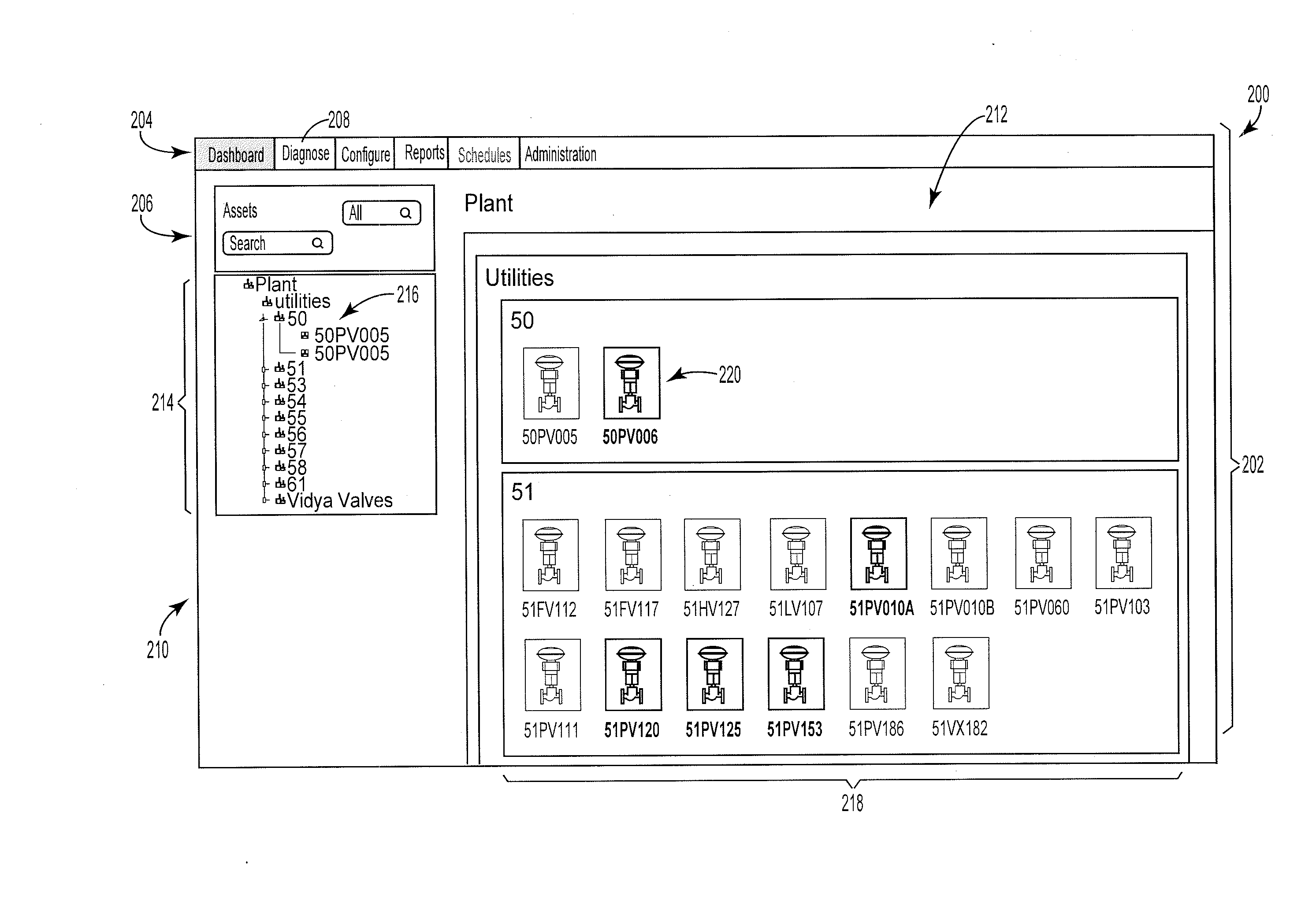
The patent describes a new system that makes it easier for people to diagnose problems with devices in the field. The system uses a web browser to deliver information to users in a simple way, without requiring them to install anything. The system works on different types of devices and allows users to access information from anywhere. This makes device diagnosis much easier and more user-friendly.

Problems solved by technology

Problems with valve assemblies on the process line may disrupt the process and / or prevent the process line from achieving the necessary process parameters.
The resulting disruptions can lower yields and reduce quality.
In large refineries, chemical plants, and power plants, disruptions can also lead to significant expense from process downtime that is necessary to troubleshoot and repair the problematic devices.
Migration of display requirements to web-based user interfaces has exposed some limitations in conventional tools.
Many of these tools are often unable to convey “live” or real-time data to a browser; instead providing static displays with limited functionality.
Moreover, these tools are likely built in a manner that is platform-specific and, thus, are not readily compatible with mobile devices that have screens that come in a variety shapes, sizes, and differing form factors.

Method used


Image

  • Method and system for generating a user interface for device diagnostics of a valve assembly and implementation thereof
  • Method and system for generating a user interface for device diagnostics of a valve assembly and implementation thereof
  • Method and system for generating a user interface for device diagnostics of a valve assembly and implementation thereof

Examples


Embodiment Construction

[0023]Advances in technology that relate to data transmission, data storage, and data processing allow plant owners and operators to monitor performance of devices at a very granular level. By implementing appropriate analysis, plant owners and operators can often predict with great accuracy the potential for failure in a singular device before problems can occur and disrupt operation of a plant or a process line. Such foresight is critical for the plant operator to make judgments about maintenance and repair schedules, to reduce labor costs, and to maintain efficient operation of the plant or process line.

[0024]Conventional tools that allow the plant operator to perform device diagnostics have not kept pace with the ever-expanding amount of data. It has been found, for example, that many conventional tools have interfaces that complicate access to the wealth of information that is available to the individuals that are responsible for oversight of the facility. These interfaces ofte...


PUM


Abstract

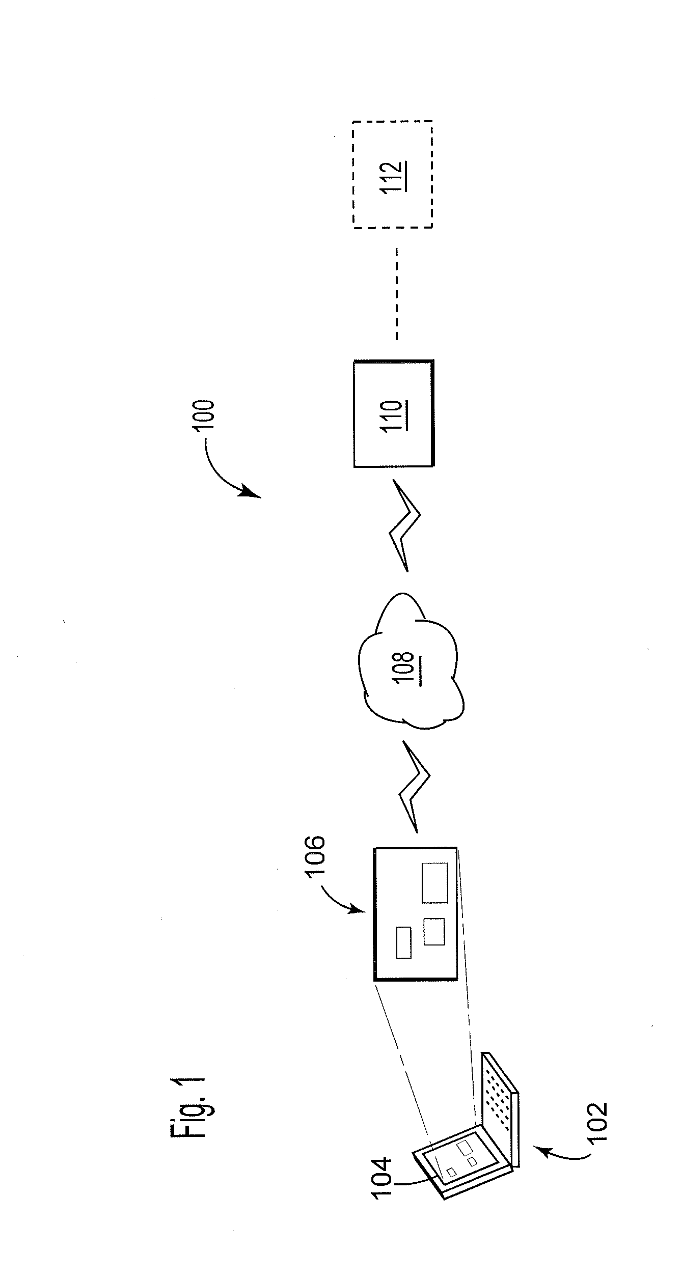
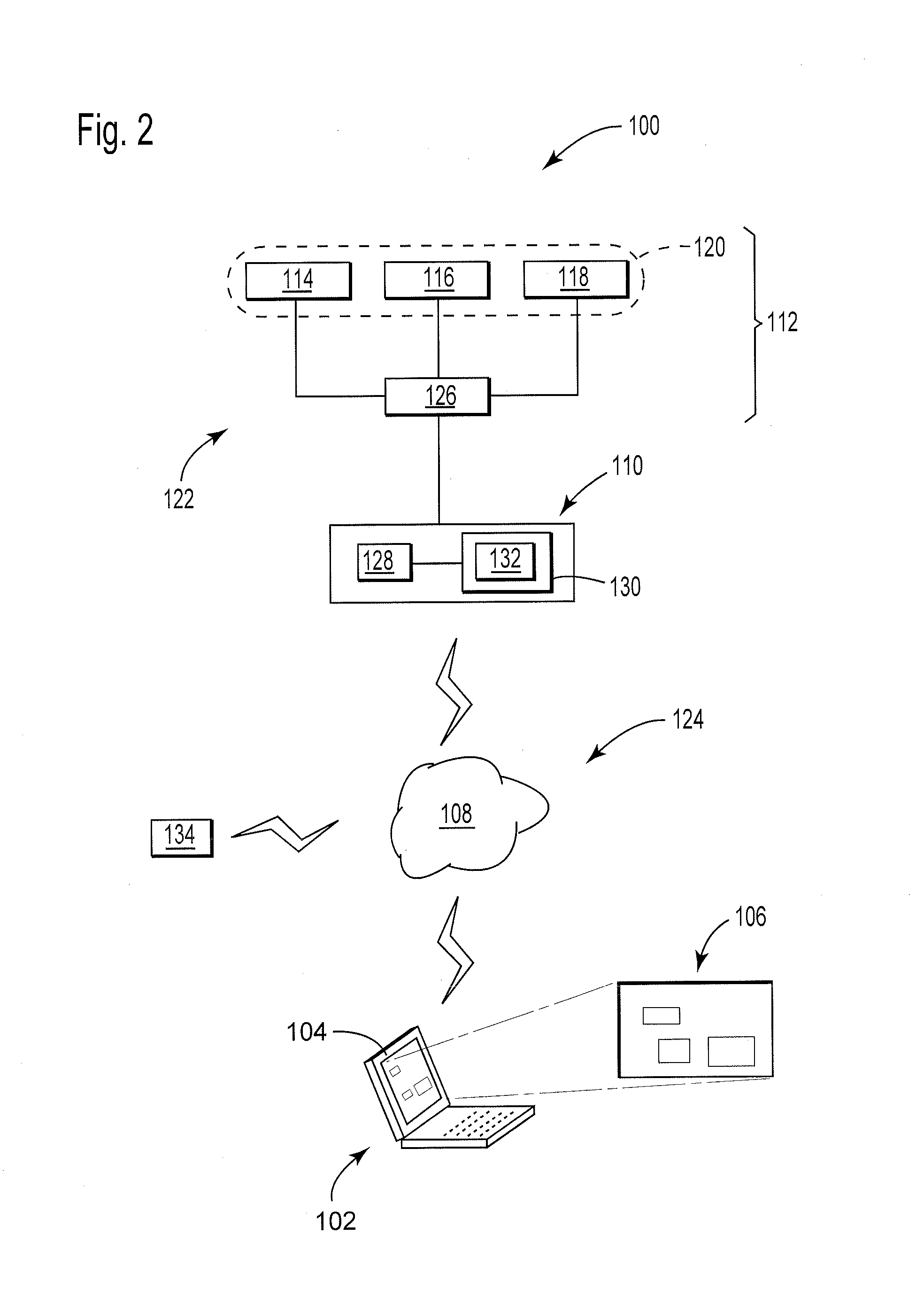
A system with a server configured to generate data for display on a first computing device. The server configured to receive a query over a network from a web browser launched on the first computing device and to generate an output with data for transmission over the network to the first computing device. The data generates a user interface on the web browser that configures the web browser to display information about the plurality of valve assemblies. In one example, the user interface is configured to conform to a form factor that defines physical attributes of the display on the first computing device. The user interface is also configured to receive a user selection from an end user that defines the query to change the information on the user interface to relate to an individual valve assembly from among the plurality of valve assemblies.

Description

CROSS-REFERENCE TO RELATED APPLICATIONS[0001]This application claims the benefit of priority to U.S. Provisional Application Ser. No. 61 / 976,243, filed on Apr. 7, 2014, and entitled “USER INTERFACE.” The content of this application is incorporated herein by reference in its entirety.BACKGROUND[0002]The subject matter disclosed herein relates to diagnostics and diagnostic tools to monitor performance of valve assemblies with particular discussion about a method and system to generate a user interface on a web browser that allows an end user to navigate to real-time data that relates to operation of an individual valve assembly.[0003]Process lines may include many varieties of flow controls. These process lines typically transfer fluids for use in the chemical industry, refining industry, oil & gas recovery industry, and the like. Examples of the flow controls include pneumatic and electronic valve assemblies (collectively, “valve assemblies”) that regulate a flow of process fluid (e....

Claims


Application Information

Patent Timeline
Patent Type & Authority Applications(United States)
IPC IPC(8): G06F3/0484G06F3/0482H04L29/08G06F17/30
CPCG06F3/04842H04L67/10G06F3/0482G06F17/30864G06F9/451G06F16/951
Inventor BUTLER, PETERMCADAMS, KARENMUNDUNURU, RAMA KRISHNA RAJUSAHNI, URVASHI
Owner DRESSER LLC
Learn More