Asynchronous machine with optimized distribution of electrical losses between stator and rotor

a technology of asynchronous machines and rotors, applied in the direction of windings, dynamo-electric components, transportation and packaging, etc., to achieve the effects of high torque density, improved suitability for use, and higher continuous torqu

Active Publication Date: 2015-10-29
ROBERT BOSCH GMBH
View PDF3 Cites 4 Cited by
  • Summary
  • Abstract
  • Description
  • Claims
  • Application Information

AI Technical Summary

Benefits of technology

The present invention provides asynchronous machines that can be used in electric motor vehicles or electric hybrid vehicles. These machines provide higher continuous torque and high torque densities, making them more suitable for use in these vehicles.

Problems solved by technology

However, in contrast to many other types of electrical machines, magnets in the form of permanent magnets or electromagnets that are supplied with energy from the exterior are not provided on the rotor that can rotate relative to the stator.

Method used


Image

  • Asynchronous machine with optimized distribution of electrical losses between stator and rotor
  • Asynchronous machine with optimized distribution of electrical losses between stator and rotor
  • Asynchronous machine with optimized distribution of electrical losses between stator and rotor

Examples


Embodiment Construction

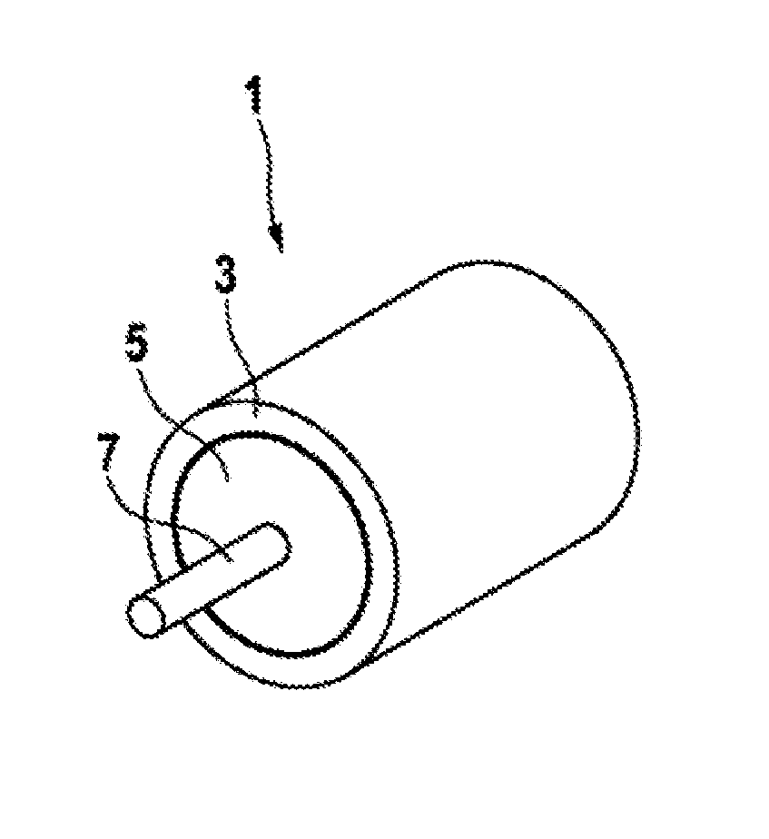
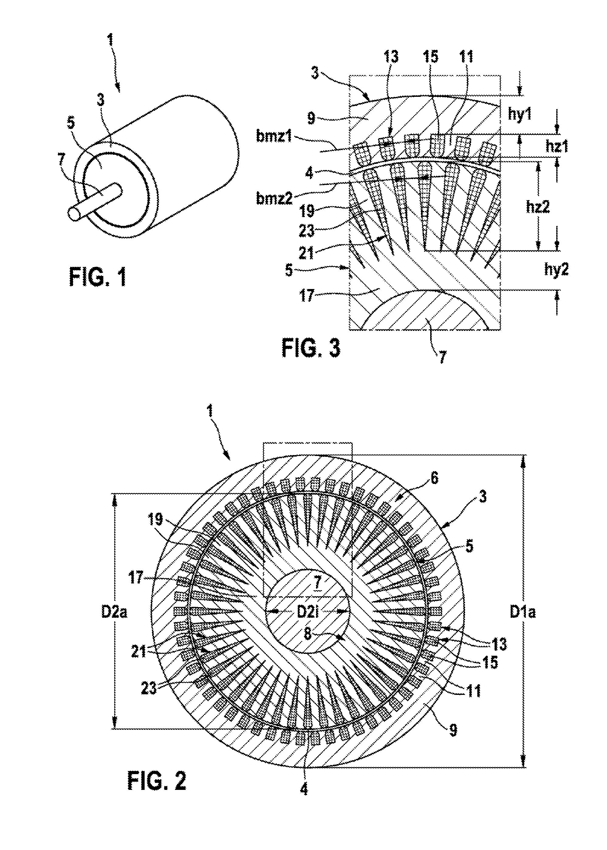
[0032]FIG. 1 illustrates an asynchronous machine 1 in accordance with an embodiment of the present invention. The asynchronous machine 1 comprises a stator 3, a rotor 5 and a shaft 7. The stator 3 surrounds the rotor 5 in an annular manner. The rotor 5 is consequently received within the stator 3 in such a manner as to be able to rotate about the shaft 7. The stator 3 and rotor 5 comprise a cylindrical form.

[0033]FIGS. 2 and 3 illustrate an electrical machine 1 in the cross section and also an enlarged section of such a cross section. A small gap 4 is embodied between the stator 3 and the rotor 5. Both the stator 3 and also the rotor 5 comprise a plurality of lamellae 6, 8 that are arranged in the axial direction one after the other.

[0034]The stator 3 comprises a stator yoke 9 that lies on the exterior. The stator yoke 9 is annular or rather cylindrical in shape. A dimension of the stator yoke 9 is described in the radial direction as stator yoke height hy1. Stator teeth 11 project ...


PUM


Abstract

The invention relates to an asynchronous machine (1) as can be used particularly in electric vehicles or hybrid vehicles. The asynchronous machine (1) has a rotor (5) and a stator (3). The asynchronous machine is designed and controlled in such a manner that it has a pole pair number p of p=3. Because of the reduced yoke saturation that can consequently be achieved, the stator yoke (9) can be designed with a lesser height hy1, such that a ratio of the outer rotor diameter D2a to the outer stator diameter D1a can assume values between 0.7 and 0.8. As a result, enlarged rotor teeth (19) and correspondingly enlarged rotor grooves (21) can be formed in the rotor (5), such that electrical losses in the material in the rotor grooves (21) acting as the rotor coil element (23) are smaller in comparison to conventional asynchronous machines. The electrical losses occurring to a greater extent in the stator (3) compensating for this lead to a lesser warming of the stator (3) than would be the case with the rotor (5) as the stator (3) can be cooled by simple means. Overall, a higher continuous torque can thus be achieved with the asynchronous machine (1) according to the invention.

Description

BACKGROUND OF THE INVENTION[0001]The present invention relates to an asynchronous machine by way of example in the form of an electrical asynchronous motor or a generator.[0002]Electrical machines are being developed in order in the future by way of example to render it possible to drive electric vehicles or hybrid vehicles in an electrical manner or rather to be able to recoup kinetic energy of the vehicle into electrical energy. The electrical machine can function either as a motor or as a generator.[0003]Various electrical machines are currently being further developed in particular for use in vehicles. In particular, efforts are being undertaken to optimize asynchronous machines for use in vehicles. Above all, for future road-going vehicles, the asynchronous machine for this purpose on the one hand should be as small and light as possible and on the other hand should be highly efficient whilst outputting as much power as possible and providing the maximum torque.[0004]Asynchrono...

Claims


Application Information

Patent Timeline
Patent Type & Authority Applications(United States)
IPC IPC(8): H02K3/28H02K3/12H02K17/16
CPCH02K3/28H02K3/12H02K17/16H02K1/165H02K17/20H02K2213/03Y02T10/64
Inventor HEUSER, PATRICKRUIZ DE LARRAMENDI, MIGUELHERRANZ GRACIA, MERCEDES
Owner ROBERT BOSCH GMBH
Why Eureka
Try Eureka