Visual-based obstacle detection method and apparatus for mobile robot

a visual-based obstacle and detection method technology, applied in the field of robot control technologies, can solve the problems of low anti-interference ability, high cost, and methods limited to binocular cameras

Active Publication Date: 2015-11-05
SUPERD TECH CO LTD
View PDF6 Cites 43 Cited by
  • Summary
  • Abstract
  • Description
  • Claims
  • Application Information

AI Technical Summary

Benefits of technology

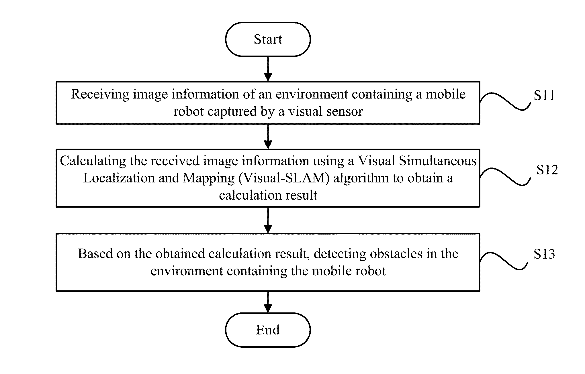
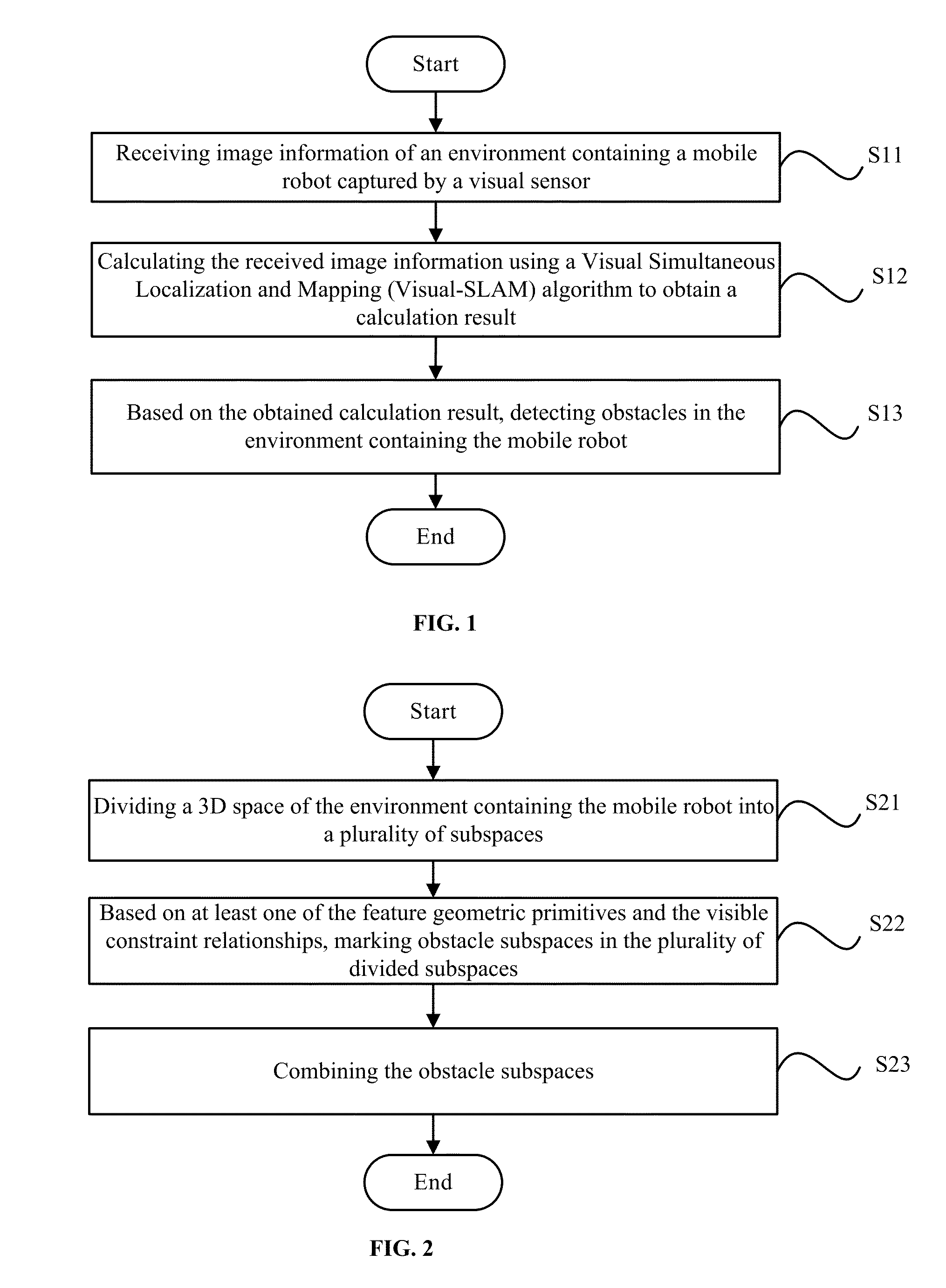
[0060]Because the image information received by the visual sensor is calculated using the Visual-SLAM algorithm, and the obstacles in the environment containing the mobile robot can be directly detected based on the obtained calculation result, the computation is relatively simple comparing to traditional obstacle detection methods. Second, because the mobile robot's moving space is not restricted, the obstacle detection process can be applied to both 3D spatial movement and 2D planar movement. The mobile robot's moving space refers to the space for a mobile robot moving on the 3D or 2D environment. Also, when the image information of the environment is captured using this obstacle detection process, the type of the visual sensor is not restricted.

Problems solved by technology

However, these detection methods may have characteristics such as low anti-interference ability and high cost.
However, these methods are only limited to the binocular camera.
Also, because the parallax of the images needs to be calculated and grid storage needs to be used to store obstacle information, the computation is complex and real-time reaction capability is poor.
However, these methods can only be used to detect the obstacles on a road surface, and the scope of its application is only limited to planar motion of the robot, not suitable for space motion.

Method used


Image

  • Visual-based obstacle detection method and apparatus for mobile robot
  • Visual-based obstacle detection method and apparatus for mobile robot
  • Visual-based obstacle detection method and apparatus for mobile robot

Examples


Embodiment Construction

[0025]Reference will now be made in detail to exemplary embodiments of the disclosure, which are illustrated in the accompanying drawings. Wherever possible, the same reference numbers will be used throughout the drawings to refer to the same or like parts.

[0026]A visual-based obstacle detection apparatus may be implemented on any appropriate computing circuitry platform. FIG. 13 illustrates an exemplary computing system consistent with the disclosed embodiments. As shown in FIG. 13, the computing system 1300 may include a processor 1302, storage medium 1304, a display 1306, a communication module 1308, a database 1310, and peripherals 1312. Certain devices may be omitted and other devices may be included.

[0027]Processor 1302 may include any appropriate processor or processors. Further, processor 1302 can include multiple cores for multi-thread or parallel processing. Storage medium 1304 may include memory modules, such as ROM, RAM, flash memory modules, and mass storages, such as C...


PUM


Abstract

A visual-based obstacle detection method is provided. The method includes receiving image information of an environment containing a mobile robot captured by at least one visual sensor to obtain one of a three-dimensional space and a two-dimensional plane, and extracting and matching feature geometric primitives based on the received image information. The method also includes reconstructing coordinates of matched extracted feature geometric primitives and positions and orientations of the visual sensor and optimizing the reconstructed coordinates to obtain a calculation result, wherein the calculation result includes the feature geometric primitives, the positions and orientations of the visual sensor, as well as visible constraint relationships between the feature geometric primitives and the positions and orientations. Further, the method includes detecting obstacles in the environment containing the mobile robot based on the obtained calculation result and plotting a path for automatic motion of the mobile robot based on the detected obstacles.

Description

CROSS-REFERENCES TO RELATED APPLICATIONS[0001]This application claims priority of Chinese Application No. 201410182735.0 filed on Apr. 30, 2014, the entire contents of all of which are hereby incorporated by reference.FIELD OF THE INVENTION[0002]The present disclosure generally relates to the field of robot control technologies and, more particularly, relates to visual-based obstacle detection methods and apparatuses for mobile robots.BACKGROUND[0003]Currently, autonomous mobile robot is a rapidly developing branch of robotics, and attracts great attention in both research and industry fields. The automatic motion of the autonomous mobile robot is a cyclical automatic process. For each cycle, the autonomous mobile robot first determines which, in the external space, are obstacles and which are free space and then designs a path in the free space. Further, the autonomous mobile robot plans its motion command based on the designed path and completes the motion.[0004]In existing techno...

Claims


Application Information

Patent Timeline
Patent Type & Authority Applications(United States)
IPC IPC(8): B25J9/16G05D1/02
CPCB25J9/1666G05D1/0214G05D1/0246Y10S901/01G05B2219/39082G05B2219/40519B25J9/1697G06T2207/30244G06T2207/30261G06T7/73G06T7/579G05D1/0274G06V20/20G01V8/10
Inventor YU, SHUDA
Owner SUPERD TECH CO LTD
Why Eureka
Try Eureka