Scissors

Inactive Publication Date: 2015-11-05
PLUS CORP
View PDF6 Cites 7 Cited by
  • Summary
  • Abstract
  • Description
  • Claims
  • Application Information

AI Technical Summary

Benefits of technology

[0029]In such cases, an adjusting member is attached to the joint region, the adjustment member including a base surface contact with the outer surface of the joint region and a top surface, the base surface having a contour corresponding to the outer surface of the joint region, the top surface being flat and parallel to the imaginary surface, the joint assembly being passed through the adjusting member in a top-to-base direction. The adjustm

Problems solved by technology

If not, the relative movement of the

Method used


Image

  • Scissors
  • Scissors
  • Scissors

Examples


first embodiment

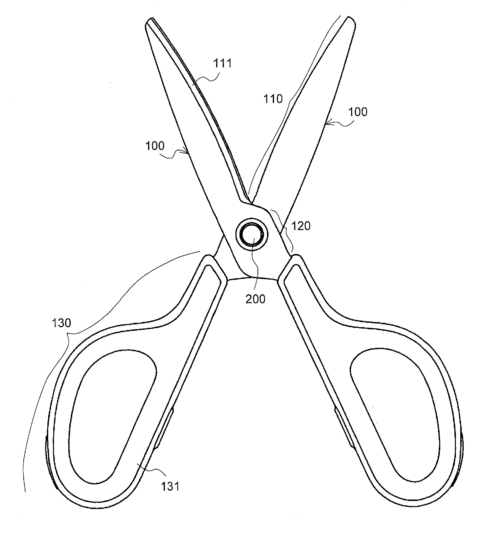
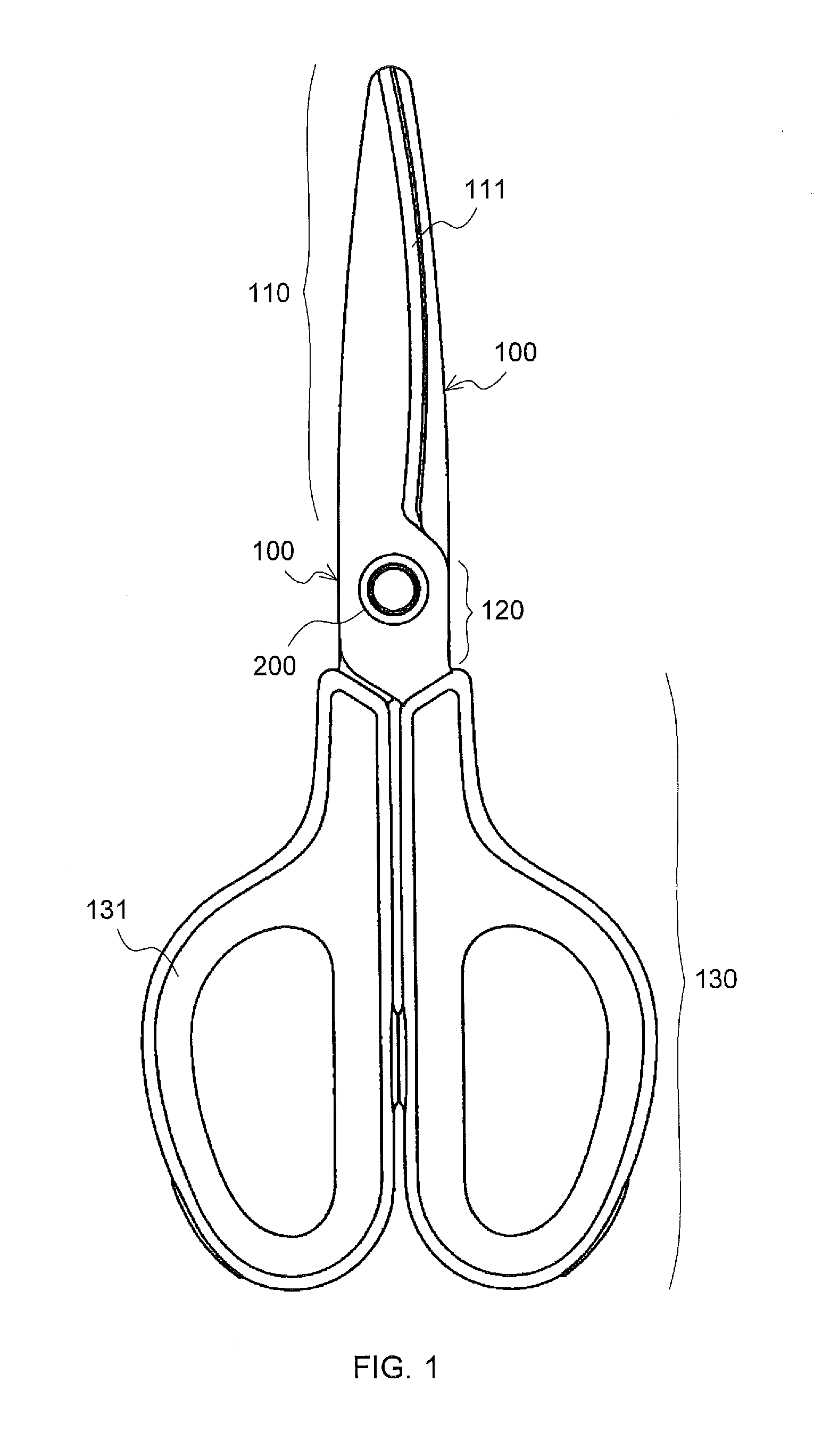
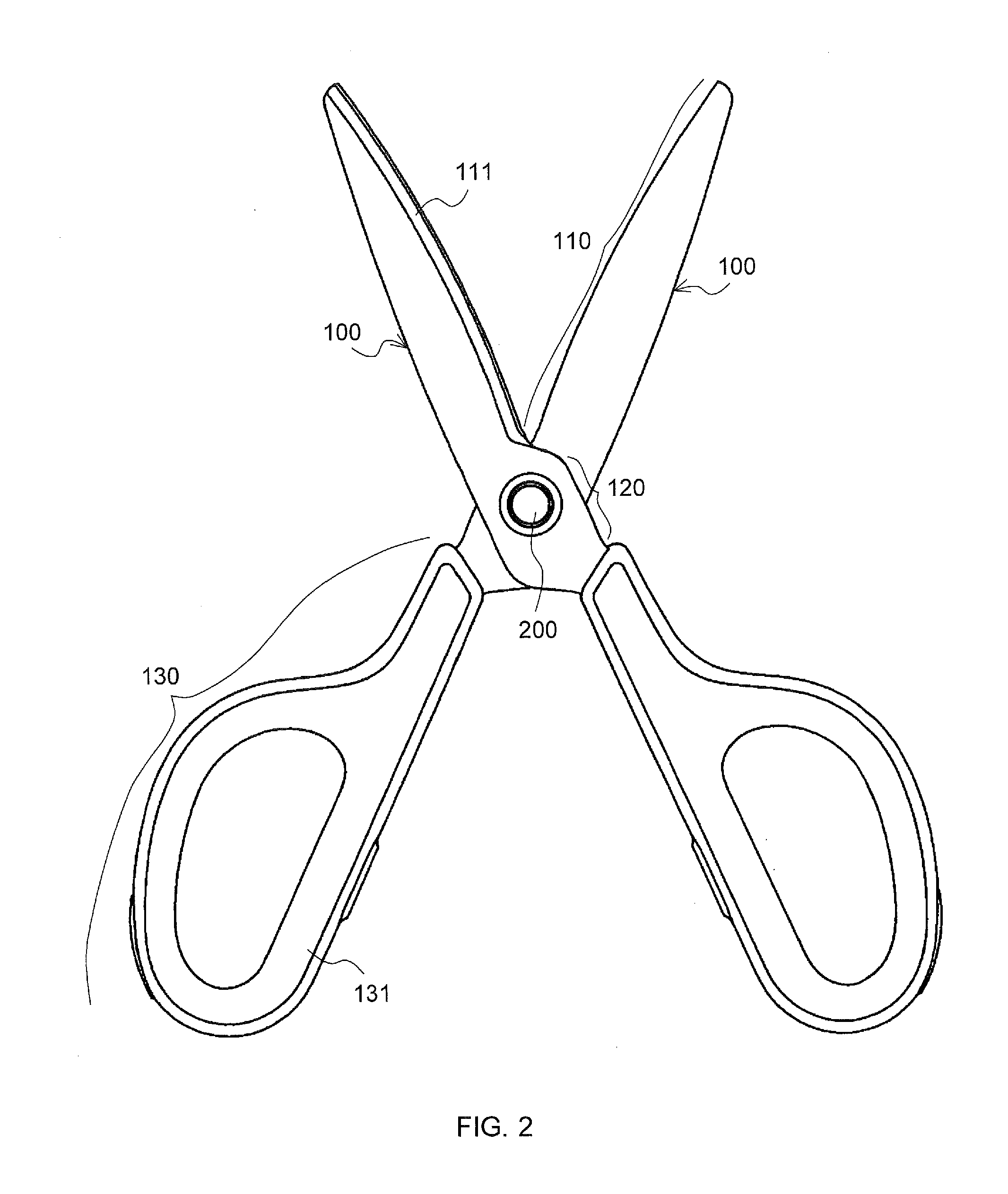
[0052]FIGS. 1 and 2 are plan views of a pair of scissors according to a first embodiment of the present invention in which cutting members described below are in their closed and opened positions, respectively, and FIG. 3 is a side view of the same scissors.

[0053]The scissors have two cutting members 100.

[0054]Each cutting member 100 includes a blade 110 at the distal side thereof, a joint region 120, and a handle 130 at the proximal side thereof.

[0055]The two cutting members 100 are pivotally joined at a joint assembly 200 in the joint region 120. In other words, the cutting members 100 can slide against each other on the joint assembly 200. How the joint regions 120 of the two cutting members 100 are joined together using the joint assembly 200 is described later.

[0056]The blades 110 are made of, for example, metal. Each blade 110 of an elongated plate-like shape comprises an edge 111. The edge 111 extends along the entire length of the blade 110 on the fore side thereof. The edge...

second embodiment

[0095]A pair of scissors of the second embodiment is basically identical the one in the first embodiment.

[0096]The pair of scissors of the second embodiment includes two cutting members similar to those described in the first embodiment. The two cutting members are joined together and can pivotally move on the joint assembly.

[0097]The cutting members of the scissors of the second embodiment are identical to those in the first embodiment in that each cutting member includes a blade, a joint region and a handle and that the blade has a curved edge and the handle has a grip. The contact-free parts are formed in the respective cutting members and the areas where the contact-free parts are provided are identical to those in the first embodiment.

[0098]The only difference between the scissors in the second embodiment and the scissors in the first embodiment lies in the cross-sectional shape of the cutting member bodies.

[0099]The outer surface and the inner surface of the cutting member are...

third embodiment

[0110]A pair of scissors of the third embodiment is basically identical to the one in the first embodiment.

[0111]The pair of scissors of the third embodiment includes two cutting members similar to those described in the first embodiment. The two cutting members are joined together and can pivotally move on the joint assembly.

[0112]The cutting members of the scissors of the third embodiment are identical to those in the first embodiment in that each cutting member includes a blade, a joint region and a handle and that the blade has a curved edge and the handle has a grip. The contact-free parts are formed in the respective cutting members and the outer surface and the inner surface of each cutting member body are parallel to each other, as in the first embodiment.

[0113]The only difference between the scissors in the third embodiment and the scissors in the first embodiment lies in coverage of the contact-free parts.

[0114]The contact-free parts 140 in the first embodiment are formed ...


PUM


Abstract

To provide scissors having a smoother cut with a light feel. A pair of scissors includes two cutting members. Each cutting member includes a blade 110 having an edge, a handle having a grip, and a joint region 120. The joint regions 120 of the cutting members are pivotally joined together using a joint assembly so that the cutting members can pivotally move. Each of the edges is curved so that an angle between the edges is kept within a range between 27° and 43° when the cutting members move from an opened position forming an angle of 30° therebetween to a closed position. A contact-free part 140 which is a recess is formed in the inner surface of the blade 110. The contact-free part 140 extends beneath the joint assembly.

Description

CLAIM OF PRIORITY TO RELATED APPLICATION[0001]The application claims priority from Japanese Patent Application No. 2014-095126 filed May 2, 2014, the disclosure of which is incorporated herein by reference in its entirety.BACKGROUND OF THE INVENTION[0002]1. Technical Field[0003]The present invention relates to scissors.[0004]2. Background Art[0005]Scissors and shears have long been used for different purposes at different places such as office places, kitchens, barber shops, and beauty shops. Tailoring shears, fabric shears, craft scissors, and food scissors are examples. (The term “scissors” is used collectively for scissors, shears, and any other cutting / shearing tools having a similar appearance, function, and configuration.)[0006]Typical scissors include two cutting members joined together with a joint assembly so that they can be opened and closed on the joint assembly. Each cutting member includes a blade, a handle, and a joint region. The blade and the handle are opposite to ...

Claims


Application Information

Patent Timeline
IPC IPC(8): B26B13/28B26B13/06
CPCB26B13/06B26B13/28
Inventor WAKABAYASHI, MITSURUKOZAKAI, TETSUOABE, SHINYA
Owner PLUS CORP
Why Eureka
Try Eureka