Power supply system, power conversion apparatus, and measurement point switching apparatus

a technology of power supply system and conversion apparatus, applied in emergency power supply arrangements, dc-ac conversion without reversal, greenhouse gas reduction, etc., can solve the problem of not being able to obtain a sufficient heat quantity for hot water supply, and achieve the effect of reducing the amount of grid power, reducing energy costs, and improving cogeneration efficiency

Active Publication Date: 2015-11-05
PANASONIC INTELLECTUAL PROPERTY MANAGEMENT CO LTD
View PDF4 Cites 26 Cited by
  • Summary
  • Abstract
  • Description
  • Claims
  • Application Information

AI Technical Summary

Benefits of technology

[0013]According to the configuration of the invention, because the output of the cogeneration device is controlled based on the current flowing through the main breaker, received from the grid power source, the cogeneration device supplies the electricity also to a load that receives feeding of power via the main breaker. Therefore, in combination of the cogeneration device and a power supply other than the grid power source, it is possible to enhance availability of the cogeneration device. In addition, the enhancing of the availability of the cogeneration device causes a reduction in the amount of grid power to be purchased from the grid power source, and therefore, it is possible to contribute to a reduction in energy costs, and further secure heat quantity to be required for supplying hot water.

Problems solved by technology

In particular, in the configuration of using the fuel battery only for purpose of compensating for power shortage, it may be impossible to obtain a sufficient heat quantity for supplying hot water because of a small amount of power generated by the fuel battery.

Method used


Image

  • Power supply system, power conversion apparatus, and measurement point switching apparatus
  • Power supply system, power conversion apparatus, and measurement point switching apparatus
  • Power supply system, power conversion apparatus, and measurement point switching apparatus

Examples


Embodiment Construction

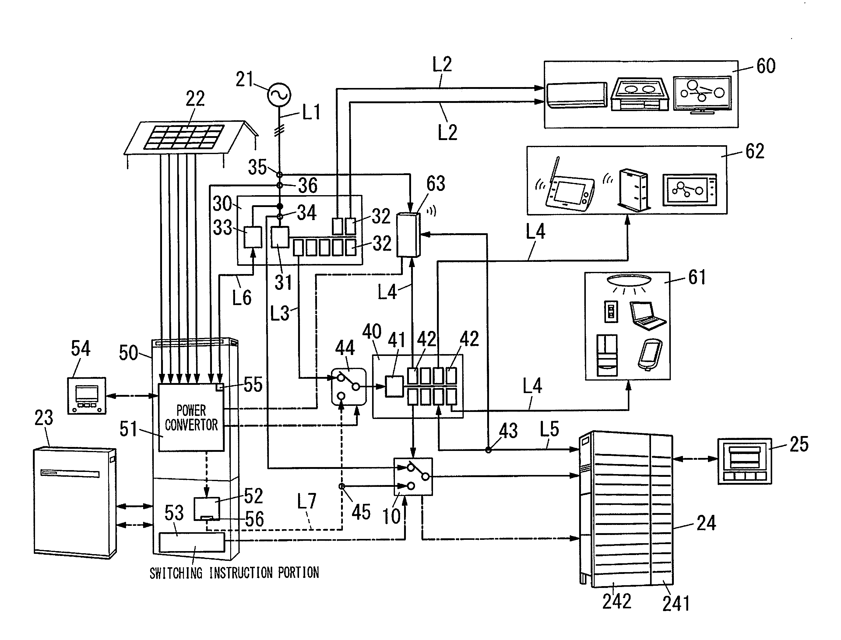
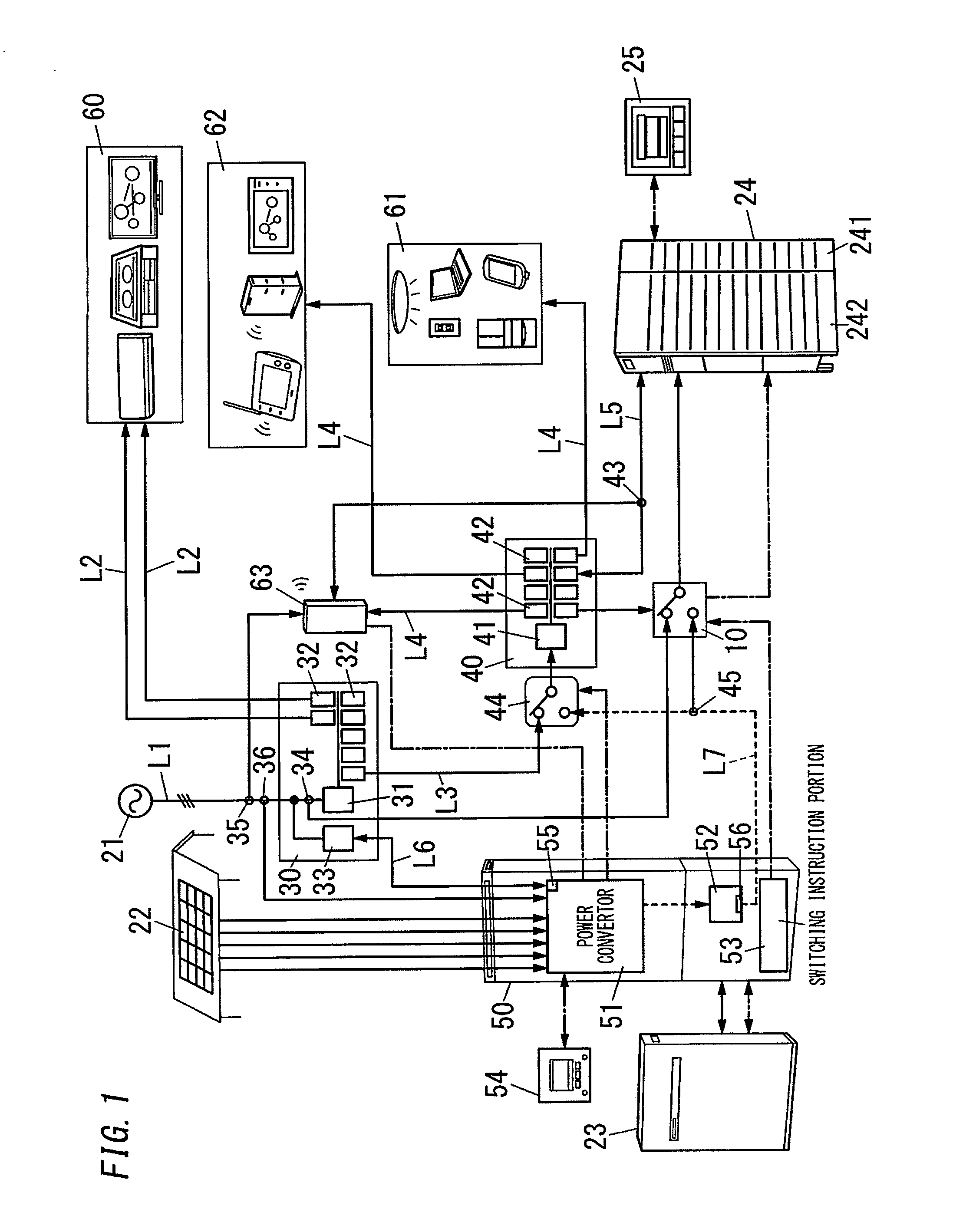
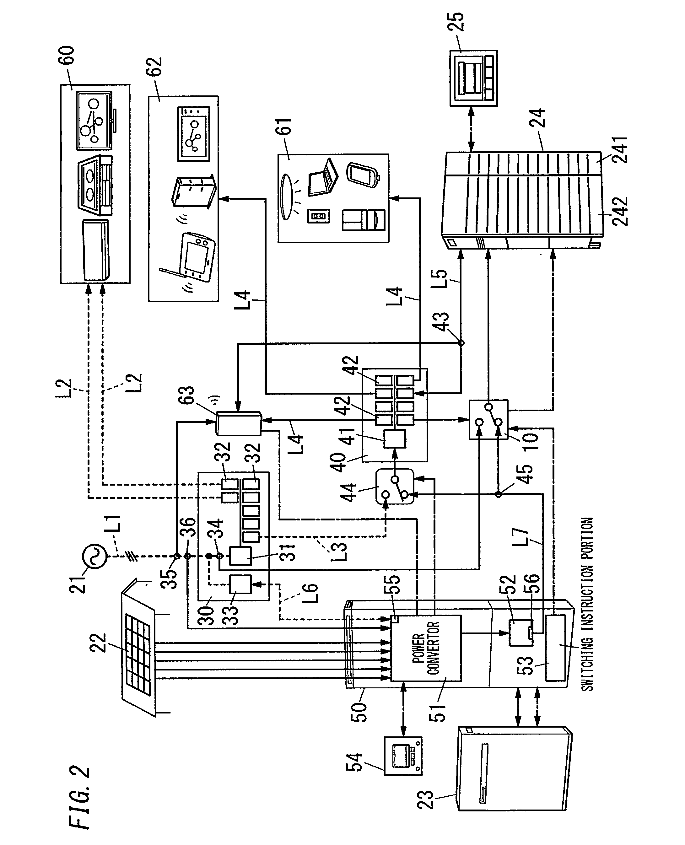
[0022]As shown in FIG. 1, a power supply system described below includes a distribution board 30, a power conversion apparatus 50, an autonomous distribution board 40, a cogeneration device (fuel battery 24) and a measurement point switching apparatus 10. The distribution board 30 includes a main breaker 31 that is connected between a grid power source 21 and a first load (loads 60). The power conversion apparatus 50 includes an interconnection terminal 55 and an autonomous terminal 56. The interconnection terminal 55 is for supplying electric power to the main breaker 31 for a period during which grid power is supplied from the grid power source 21. The autonomous terminal 56 is for extracting the electric power from the power conversion apparatus for a period during which supplying of the grid power from the grid power source 21 is stopped. The autonomous distribution board 40 is configured to receive feeding of power via the distribution board 30 for the period during which the g...


PUM


Abstract

An autonomous distribution board receives feeding of power via a distribution board for a period during which grid power is supplied from a grid power source, while receiving power via an autonomous terminal of a power conversion apparatus for a period during which supplying of grid power from grid power source is stopped. Autonomous distribution board is connected with a specific load and the like. A measurement point switching apparatus is configured to select one from a current sensor configured to monitor a current that flows through a main breaker, and a current sensor configured to monitor a current that is supplied from power conversion apparatus to autonomous distribution board. A fuel battery is configured to adjust an output thereof based on an output of the selected one so that power by fuel battery is consumed by a general load, specific load and the like.

Description

TECHNICAL FIELD[0001]The invention relates generally to power supply systems and, more particularly, to a power supply system that is used in combination of a cogeneration device and a power supply other than a grid power source. In addition, the invention relates to a power conversion apparatus to be used for this power supply system, and a measurement point switching apparatus to be used for this power supply system.BACKGROUND ART[0002]Conventionally, there has been proposed a power supply system, which is used in combination of a solar battery as a distributed power supply and a storage battery (e.g., JP 2002-171674 A (hereinafter, referred to as “Document 1”)). This type of power supply system has an advantage that a power converter can be used in common by the solar battery and the storage battery. Document 1 discloses a technique of causing excess electric power generated by the solar battery to reversely flow into an electrical grid, and preventing electric power stored in th...

Claims


Application Information

Patent Timeline
Patent Type & Authority Applications(United States)
IPC IPC(8): H02J3/12H02J7/35H02M7/44
CPCH02J3/12Y10T307/32H02J7/35H02M7/44H02J3/32H02J3/46H02J9/062Y02B70/3225Y04S20/222Y04S20/248H02J2310/64H02J2310/12H02J2300/30H02J2300/28H02J2300/20H02J2300/24H02J3/381H02J3/14Y02B10/70Y02B70/30Y02B90/10Y02E10/56Y02E10/76Y04S50/10Y02E70/30Y02P80/14Y02P80/15
Inventor INAKAGATA, SATORUNAGASATO, HIROSHIKAKU, HIROAKIITO, YOSHIKATSUANDO, KIYOSHIIHIRA, YASUHISA
Owner PANASONIC INTELLECTUAL PROPERTY MANAGEMENT CO LTD
Why Eureka
Try Eureka