Catheter assembly

a catheter and assembly technology, applied in the field of catheter assembly, can solve the problems of inconvenient assembly, long exposure to radiation or drugs during the procedure, and the predetermined configuration of the inner and outer catheter, and achieve the effect of sufficient flexibility

Inactive Publication Date: 2015-11-12
CATHRX LTD
View PDF4 Cites 0 Cited by
  • Summary
  • Abstract
  • Description
  • Claims
  • Application Information

AI Technical Summary

Benefits of technology

[0015]In an embodiment, the coiled part of the second tubular member may have a greater circumference than the coiled part of the first tubular member and the shape-imparting element may be of sufficient flexibility so that, in use, the coiled part of the second tubular member is able to be displaced into a position proximally of the coiled part of the first tubular member.
[0024]The catheter assembly may include a reinforcing element arranged about an outer surface of the first tubular member. The reinforcing element may, for example, be a braided sleeve to provide additional torquability.

Problems solved by technology

However, these treatments alleviate, rather than cure, the condition.
A disadvantage of each of the catheter system embodiments disclosed in the '996 patent is that the inner and outer catheters assume a specific, predetermined configuration after insertion.
This additional time means that the patient, and in some cases the physician, has longer exposure to radiation or drugs required during the procedure.
A further disadvantage of the catheter system embodiments disclosed in the '996 patent is that the inner catheter extends through an opening in the sidewall of the outer catheter.
It can be difficult to align the distal end of the inner catheter with the sidewall opening in the outer catheter.
The sidewall opening also complicates manufacture of the outer catheter and represents a location of potential weakness in the outer catheter.

Method used


Image

  • Catheter assembly
  • Catheter assembly
  • Catheter assembly

Examples


Embodiment Construction

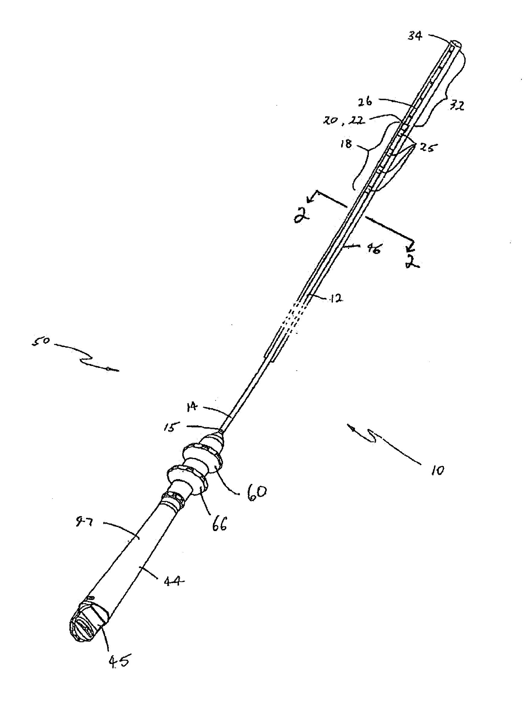
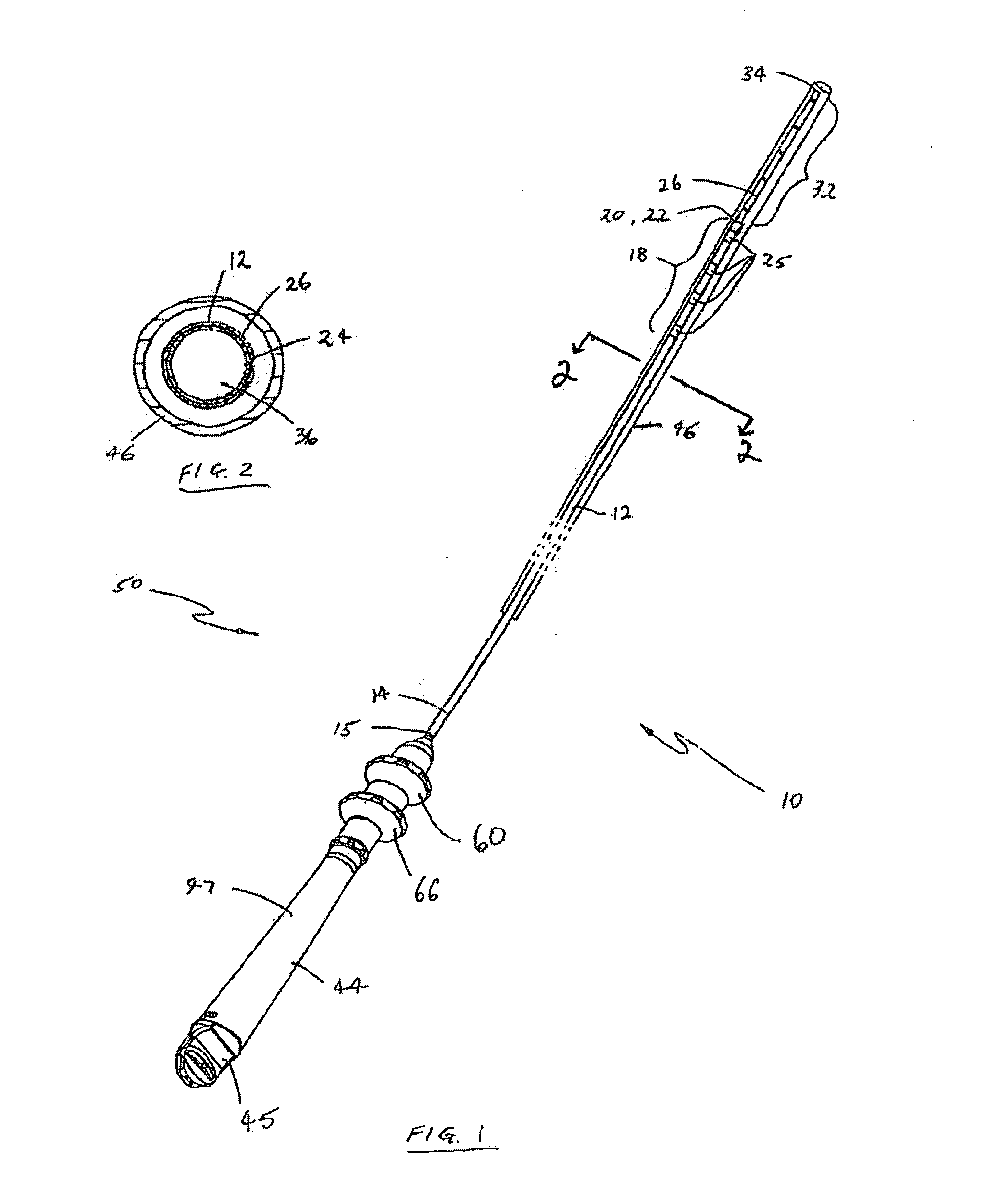
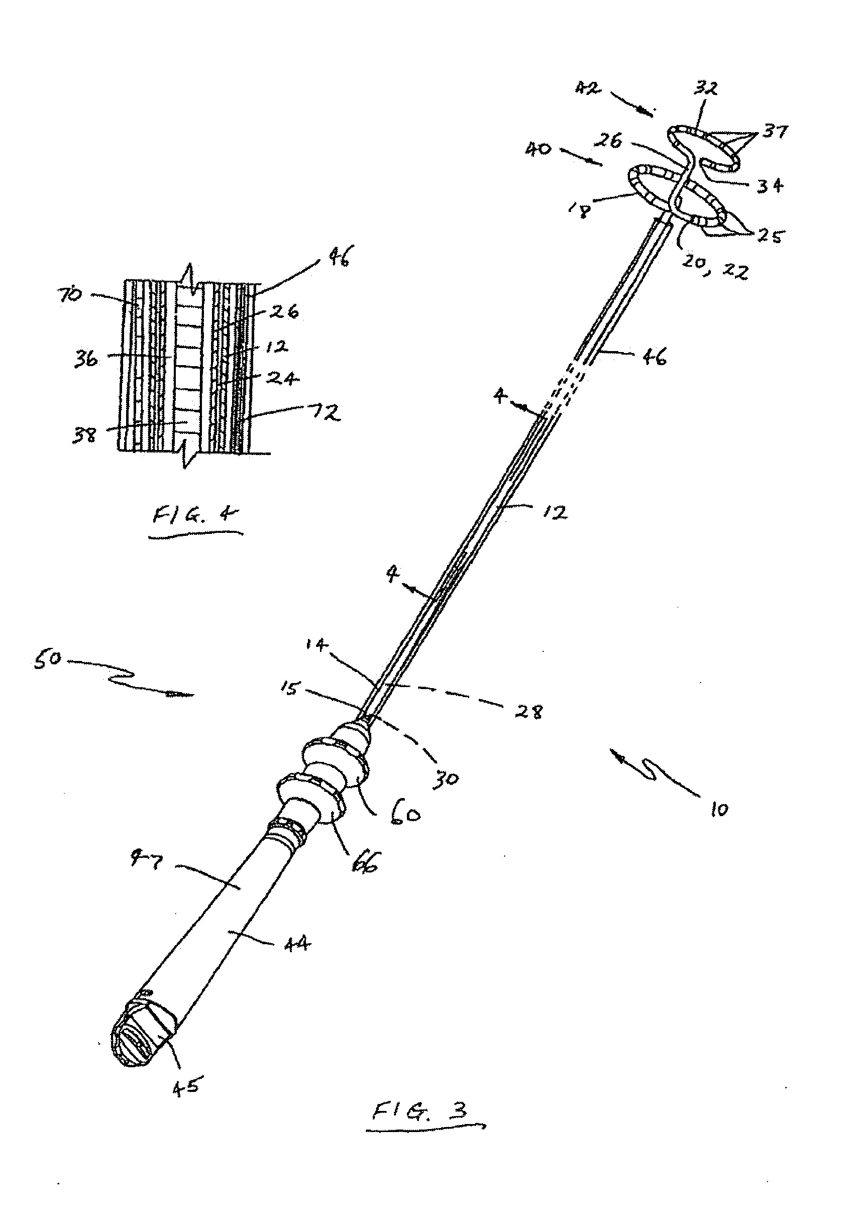
[0055]In the drawings, reference numeral 10 generally designates an embodiment of a catheter assembly. The catheter assembly 10 includes a first elongate tubular member 12 having a proximal end portion 14 defining a proximal end 15 and a distal end portion 18 defining a distal end 22. An opening 20 is located at the distal end 22 of the first tubular member 12. The tubular member 12 defines a lumen 24 extending between the proximal end 15 and the distal end 22. A plurality of electrodes 25 are provided at spaced intervals on the distal end portion 18 of the first elongate tubular member 12. In this embodiment, the electrodes 25 are used for ablation purposes.

[0056]A second elongate tubular member 26 is received in the lumen 24 of the first tubular member 12. In this embodiment, the second tubular member 26 is slidable axially in the lumen 24 of the first tubular member 12. The second tubular member 26 also includes a proximal end portion 28 defining a proximal end 30 and a distal en...


PUM


Abstract

A catheter assembly comprises a first elongate tubular member having a proximal end portion defining a proximal end, a distal end portion having an opening therein and defining a distal end, and at least one lumen defined between the proximal end and the distal end. A second elongate tubular member has a proximal end portion defining a proximal end, a distal end portion defining a distal end, and at least one lumen defined between the proximal end and the distal end. The second elongate tubular member is received within the at least one lumen of the first elongate tubular member, such that the distal end portion of the second elongate tubular member projects from the opening in the distal end portion of the first elongate tubular member. An elongate, shape-imparting element is receivable in the at least one lumen of at least one of the first elongate tubular member and the second elongate tubular member. The shape-imparting element imparts a non-rectilinear shape to the distal end portion of at least one of the first elongate tubular member and the second elongate tubular member.

Description

CROSS-REFERENCE TO RELATED APPLICATIONS[0001]This application is a continuation of copending U.S. patent application Ser. No. 13 / 125,033, filed Apr. 19, 2011, which will issue Jul. 21, 2015 as U.S. Pat. No. 9,084,869, which is a national phase entry under 35 U.S.C. §371 of International Patent Application PCT / AU2009 / 001421, filed Oct. 30, 2009, published in English as International Patent Publication WO 2010 / 048676 A1 on May 6, 2010, which claims the benefit under Article 8 of the Patent Cooperation Treaty to U.S. Provisional Patent Application Ser. No. 61 / 110,522 dated Oct. 31, 2008, the disclosures of each of which are incorporated herein by reference in their entirety.TECHNICAL FIELD[0002]The present disclosure relates, generally, to a catheter assembly and, more particularly, to a catheter assembly having a first catheter tube and a second catheter tube that are both able to be introduced into an anatomical site through a single introduction path.[0003]The catheter assembly has ...

Claims


Application Information

Patent Timeline
Patent Type & Authority Applications(United States)
IPC IPC(8): A61M25/01A61M25/00
CPCA61M25/0152A61M25/0041A61M25/0043A61M2210/125A61B18/1492A61M2025/0163A61M25/0147A61M2025/0161A61B5/04A61M2025/0004A61B5/24
Inventor ANDERSON, NEIL LAWRENCECHONG, EVAN KA-LOKEOGLE, DAVIDPANOS, JAMES
Owner CATHRX LTD
Why Eureka
Try Eureka