Device system having a positioning apparatus for determining a bore center point

a positioning apparatus and device technology, applied in the direction of drilling/boring measurement devices, work benches, manufacturing tools, etc., can solve the problems of positioning apparatuses attached to the drive shaft, and achieve the effect of simple assembly and disassembly of the positioning apparatus, accurate center point determination, and quick center point determination

Inactive Publication Date: 2015-11-12
HILTI AG
View PDF10 Cites 13 Cited by
  • Summary
  • Abstract
  • Description
  • Claims
  • Application Information

AI Technical Summary

Benefits of technology

[0008]Preferably, the fastener has a magnet. The magnet permits a simple assembly and disassembly of the positioning apparatus and it affixes the positioning apparatus onto the guide rail. The positioning apparatus according to the invention permits a quick determination of the center point of a hole that is to be drilled.
[0009]Preferably, the positioning apparatus has a guide on a side facing the guide rail. Via this guide,

Problems solved by technology

A drawback of the known positioning apparatuses for determining the center point o

Method used


Image

  • Device system having a positioning apparatus for determining a bore center point
  • Device system having a positioning apparatus for determining a bore center point
  • Device system having a positioning apparatus for determining a bore center point

Examples


Embodiment Construction

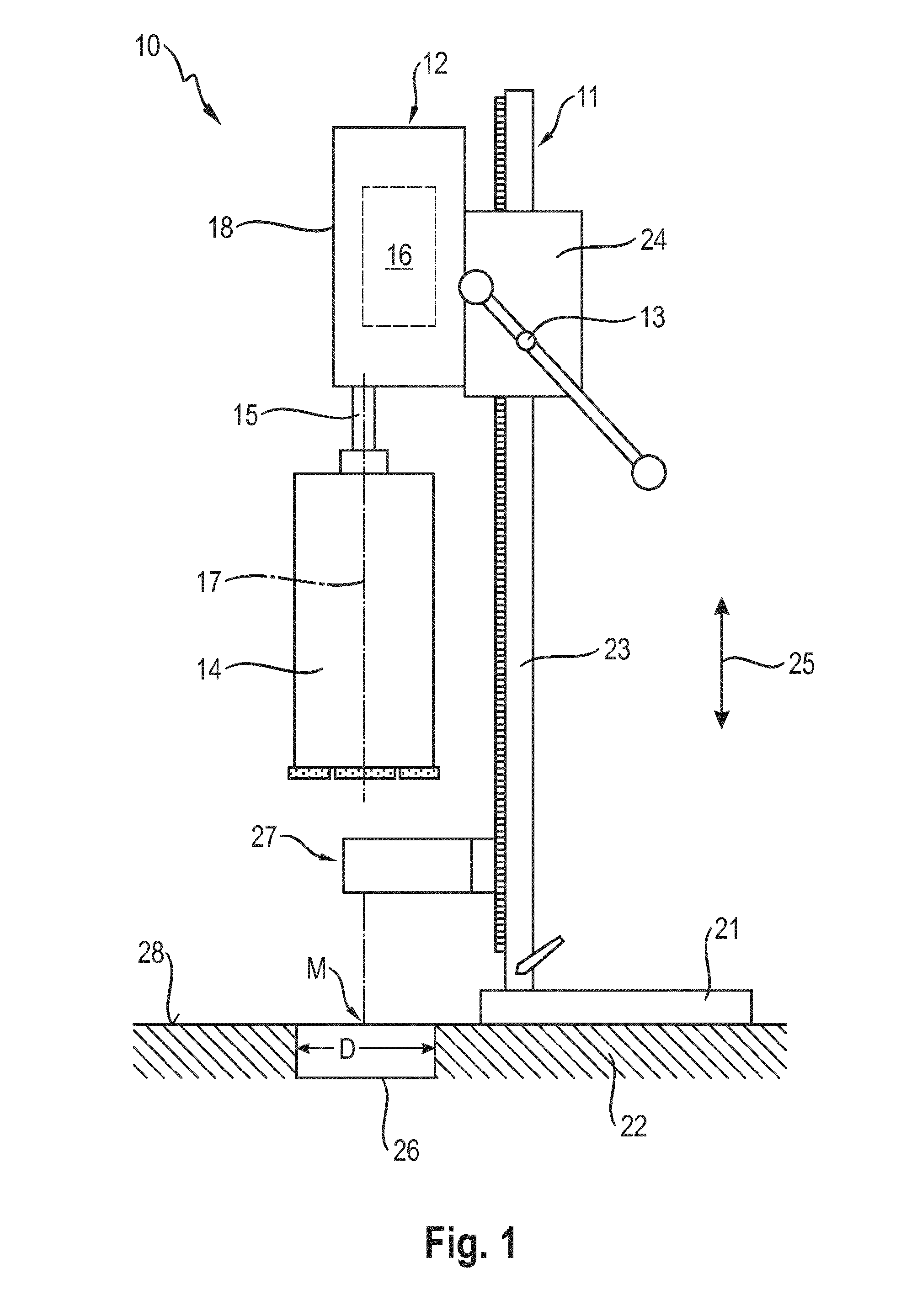
[0017]FIG. 1 shows a device system 10 according to the invention, consisting of a tool stand 11, a power tool 12 arranged movably on the tool stand 11, and a feed mechanism 13 for moving the power tool 12 along the tool stand 11.

[0018]The power tool is configured as a core drill 12 and comprises a processing tool configured as a drilling head 14 that is arranged on a drive shaft 15 and that is driven by a drive means 16 around an axis of rotation 17. The term “drive means” refers to the combination of all of the drive components for the drilling head 14, except for the drive shaft 15. The drive means 16 shown schematically in FIG. 1 is arranged in a device housing 18.

[0019]The tool stand 11 consists of a baseplate 21 that is attached to a substrate 22 that is to be worked, and of a guide rail 23 that is connected to the baseplate 21. The core drill 12 is arranged on the guide rail 23 via a guide block 24, and it can be moved by means of the feed mechanism 13 along the guide rail 23 ...


PUM

PropertyMeasurementUnit
Distanceaaaaaaaaaa

Abstract

A device system (10) for drilling a hole (26) having a center point (M) in a substrate (22), said device system including a power tool (12) with a drilling head (14) that can be attached to a drive shaft (15) and that can rotate around an axis of rotation (17), a tool stand (11) with a guide rail (23) and a guide block (24) to hold the power tool (12), a feed mechanism (13) for moving the power tool (12) along the guide rail (23), and a positioning apparatus (27) for determining the center point (M) of the hole (26) that is to be drilled, whereby the positioning apparatus (27) includes an emitter (34) to emit one or more laser beams.

Description

[0001]The present invention relates to a device system with a positioning apparatus for determining the center point of a drill hole.BACKGROUND[0002]German utility model DE 20 2004 005 221 U1 describes a device system consisting of a tool stand, a power tool arranged movably on the tool stand, and a feed mechanism for moving the power tool along the tool stand. The power tool is configured as a core drill and comprises a drilling head that is attached to a drive shaft and that can rotate around an axis of rotation. The drilling head creates a drill hole in the substrate, said hole having a certain diameter and a center point. The tool stand comprises a guide rail and a guide block to hold the core drill, whereby the core drill is arranged on the guide rail via the guide block and can be moved along the guide rail by means of the feed mechanism.[0003]In order to align the axis of rotation with the center point of the desired drill hole, the device system has a positioning apparatus w...

Claims


Application Information

Patent Timeline
IPC IPC(8): B23B49/00B25H1/00
CPCB23B49/00B25H1/0092Y10T408/21B23B2260/092B25H1/0042
Inventor SATTLER, CHRISTIANVIDA, GABOR
Owner HILTI AG
Why Eureka
Try Eureka