Toilet Fastener Assembly and Method of Use

a technology of adjustable length and fasteners, which is applied in the direction of threaded fasteners, screws, bolts, etc., can solve the problems of reducing the service life of the bolt, so as to achieve the effect of maintenance, and reducing the cost of maintenan

Active Publication Date: 2015-11-12
DANCO
View PDF5 Cites 8 Cited by
  • Summary
  • Abstract
  • Description
  • Claims
  • Application Information

AI Technical Summary

Benefits of technology

[0007]This invention offers new advantages and provides a solution to difficulties commonly encountered during toilet installation, including without limitation eliminating the need for using hand tools when setting the toilet base; simplifying installation over a wide range of drain, closet flange, floor, and toilet configurations; and avoiding the need for large or unsightly toilet bolt caps and the cleaning problems often associated with the use of traditional toilet installation hardware and accessories. With the present invention, a plurality of coaxially alignable, cooperatively engageable fastener sections provides height adjustability without the need for sawing or breaking bolts, and facilitates the use of either a low profile bolt cap provided with the assembly or another bolt cap such as an OEM cap supplied with the toilet. The low profile bolt cap is desirably directly attachable to one of the cooperatively engageable fastener sections or to a fastener tightening tool that is incorporated in some embodiments of the apparatus of the invention.

Problems solved by technology

Such bolt covers or caps can be more difficult to clean and sanitize around during routine housekeeping.
If they are too long, however, the bolts must be shortened prior to applying the decorative cap.
These conventional bolt assemblies and methods pose several common problems that establish a need for an improved technology.
The need for using hand tools to saw off or break bolts in locations that are often cramped and confining poses a significant hindrance to both professional installers and do-it-yourself (“DIY”) consumers.
Any sawing or breaking of the bolt ends in a confined space between the toilet and a nearby wall or sink can require the installer to assume awkward positions with a limited range of movement.
Breaking the bolts can bend the bolts or damage threads, and over-tightening the nuts with a wrench can crack or fracture a toilet base.

Method used


Image

  • Toilet Fastener Assembly and Method of Use
  • Toilet Fastener Assembly and Method of Use
  • Toilet Fastener Assembly and Method of Use

Examples


Embodiment Construction

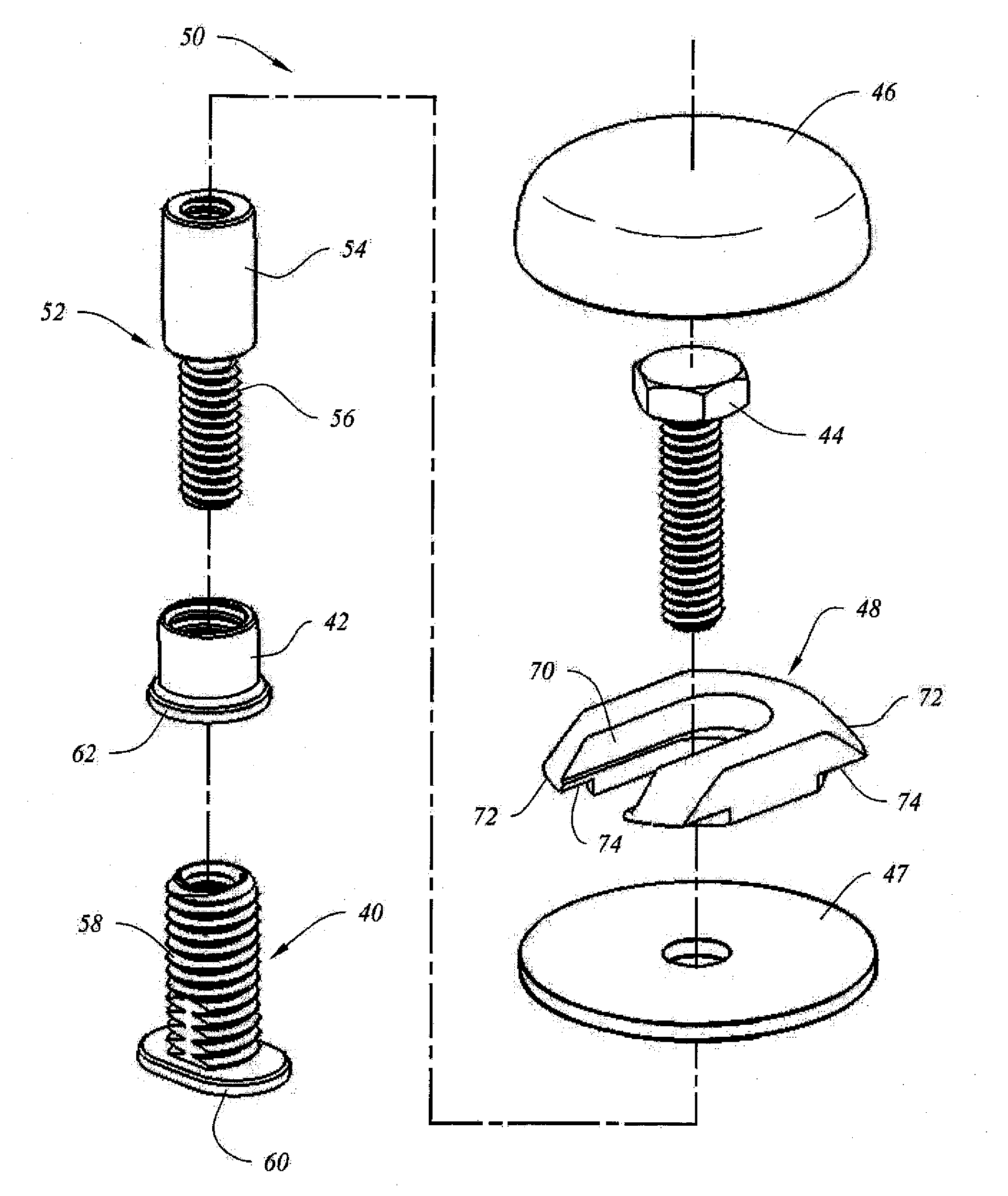
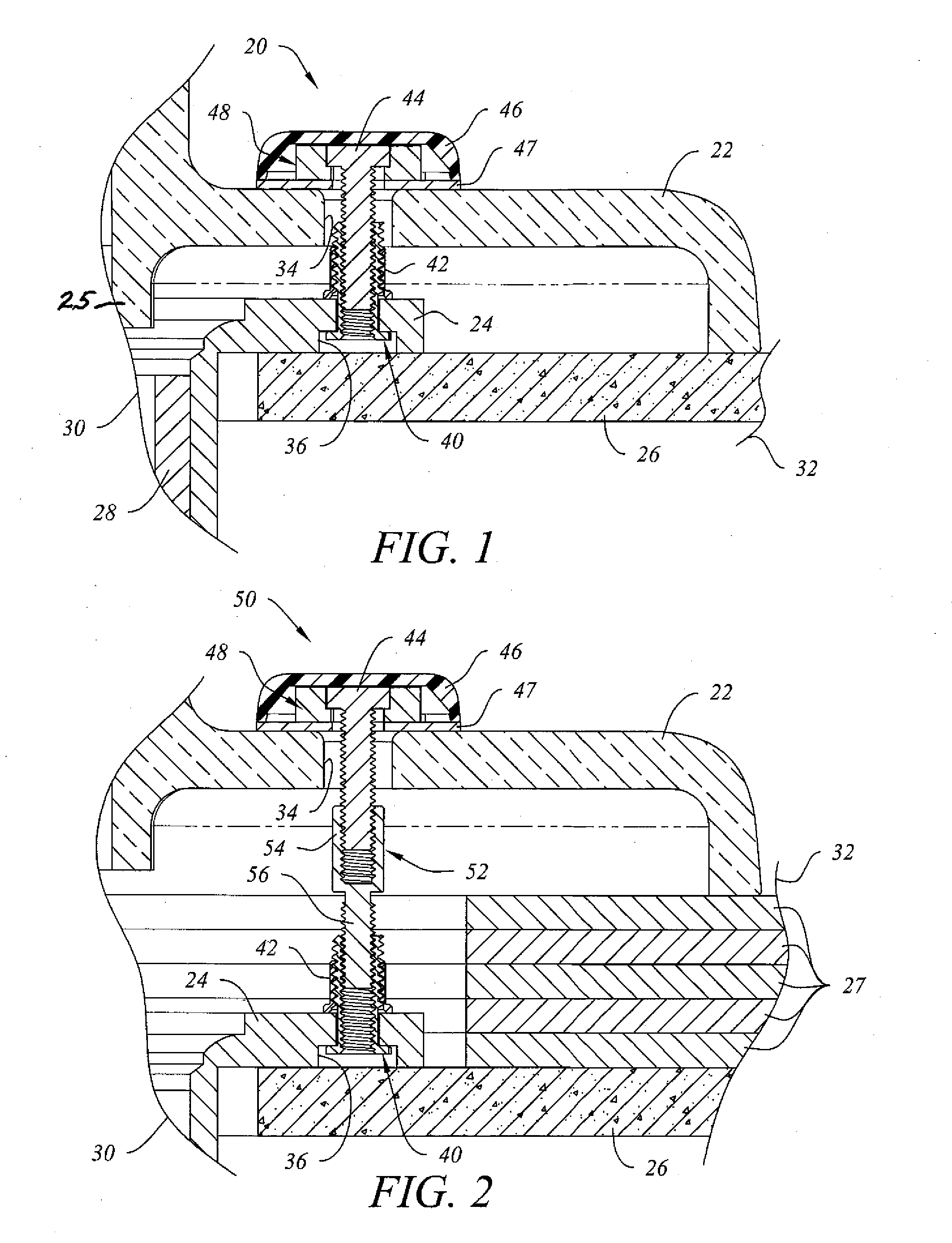
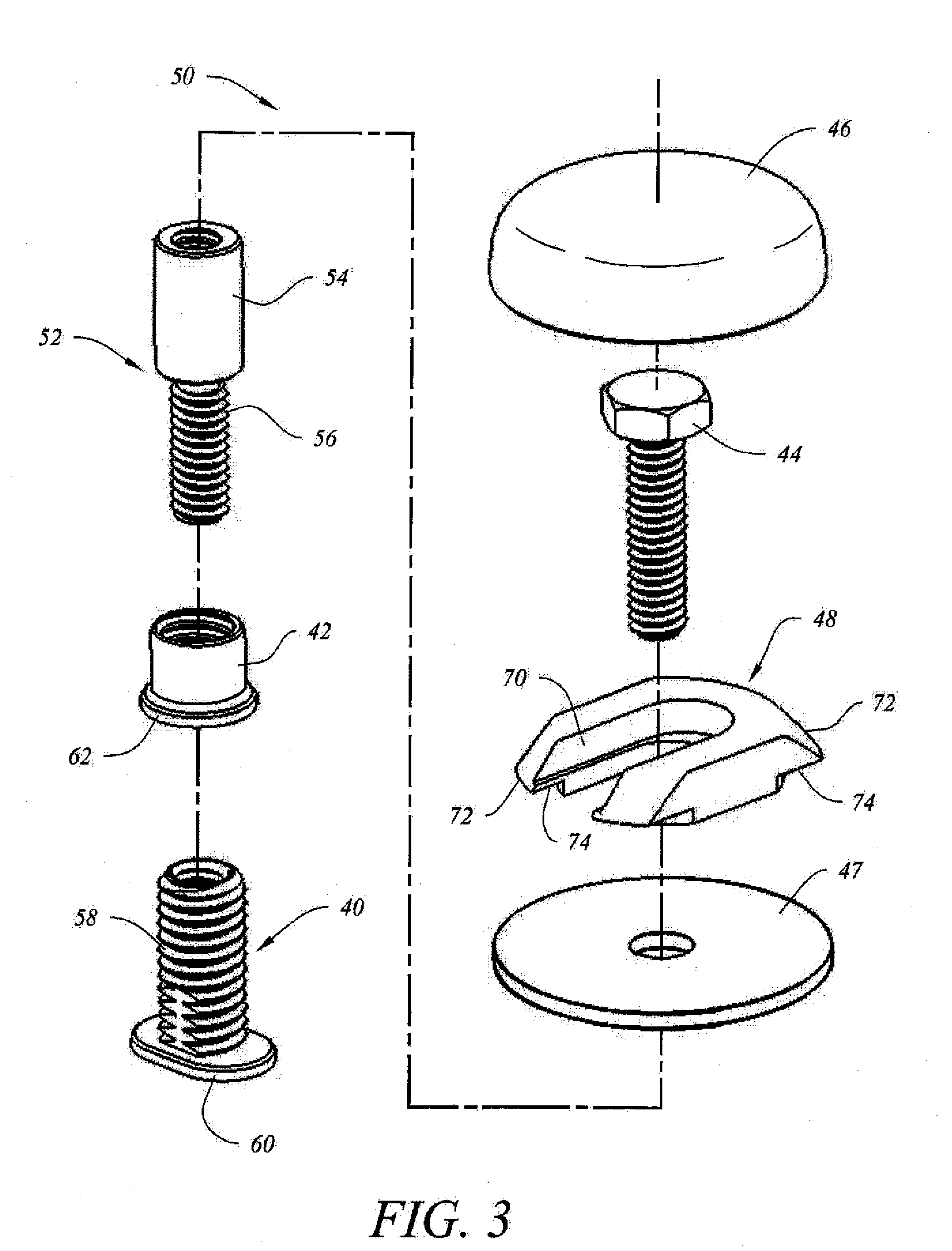
[0031]Referring to FIG. 1, a toilet fastener assembly 20 is shown as installed in a use environment in which toilet base 22 is seated over a support structure comprising a flange portion of closet collar 24 that is installed in and around an opening in subfloor 26. A fluid seal, such as a wax ring or another similarly effective fluid seal, is typically installed between the downwardly facing fluid outlet horn 25 of toilet base 22 and closet collar 24 but is not part of the subject fastener assembly and is not shown in this illustration to simplify the drawing. Closet collar 24 is depicted as installed over an upwardly facing open end of drain pipe 28, although it will be appreciated by those of skill in the art that in other installations where the subject fastener assembly is used, the structure and positional relationship of closet collar 24 and drain pipe 30 can vary from that shown in FIG. 1. Line segments 30, 32 are provided as indicators that the portions of the installation a...


PUM

PropertyMeasurementUnit
lengthaaaaaaaaaa
distancesaaaaaaaaaa
torqueaaaaaaaaaa

Abstract

An adjustable-length toilet fastener assembly and method for use wherein the constituent components are cooperatively configured to provide height adjustability without cutting or breaking parts of the assembly for various installation environments and floor configurations when securing a toilet to an underlying support such as a closet collar or other mounting flange. In one embodiment, a tightening tool provided as part of the subject assembly is engageable with and concealed by a low-profile decorative cap.

Description

FIELD OF THE INVENTION[0001]This invention relates to adjustable-length fasteners such as bolts and screws that can be used to install and secure toilets to support structures, particularly underlying support structures such as subfloors, collars, flanges, drain pipes and the like.DESCRIPTION OF RELATED ART[0002]Traditionally, a toilet is installed over a drain pipe using a closet collar secured to the subfloor in fluid communication with the drain pipe. A fluid seal such as a wax ring or other similarly effective sealing member is desirably positioned between a downwardly projecting outlet horn of the toilet base that is insertable into the closet collar to prevent fluid leakage that can otherwise occur when the toilet is flushed. In a conventional toilet installation, the toilet base is typically secured to the flange portion of the closet collar with a long threaded bolt, sometimes called a “toilet bolt” or “floor bolt” that is positioned to be insertable upwardly through an aper...

Claims


Application Information

Patent Timeline
Patent Type & Authority Applications(United States)
IPC IPC(8): E03D11/16F16B35/00
CPCE03D11/16Y10T29/49432F16B35/00F16B2/065F16B5/0233F16B5/0275F16B5/065F16B33/006F16B37/14
Inventor SCHUSTER, MICHAEL J.PORTER, DWAYNE A.
Owner DANCO
Why Eureka
Try Eureka