Systems and methods for an engine

a technology of systems and methods, applied in the direction of machines/engines, electrical control, exhaust gas treatment electric control, etc., can solve the problems of reducing the transient response time, and achieve the effect of reducing the flow of exhaust gas through the exhaust gas treatment device, increasing the thermal energy available for the turbocharger, and reducing the amount of thermal energy absorbed

Active Publication Date: 2015-11-12
GE GLOBAL SOURCING LLC
View PDF1 Cites 10 Cited by
  • Summary
  • Abstract
  • Description
  • Claims
  • Application Information

AI Technical Summary

Benefits of technology

[0006]By including a valved bypass around the exhaust gas treatment device, exhaust gas flow through the exhaust gas treatment device may be reduced during transient conditions by opening the valve. As such, the exhaust gas flow may bypass the exhaust gas treatment device resulting in a decrease of thermal energy absorbed by the exhaust gas treatment device, and an increase of thermal energy available for the turbocharger. In this manner, the turbocharger may produce a greater amount of boost, which may result in a decrease in transient response time. Further, because the exhaust gas treatment device is positioned upstream of the turbocharger, specific fuel consumption may be maintained.

Problems solved by technology

In this manner, the turbocharger may produce a greater amount of boost, which may result in a decrease in transient response time.

Method used


Image

  • Systems and methods for an engine
  • Systems and methods for an engine
  • Systems and methods for an engine

Examples


Embodiment Construction

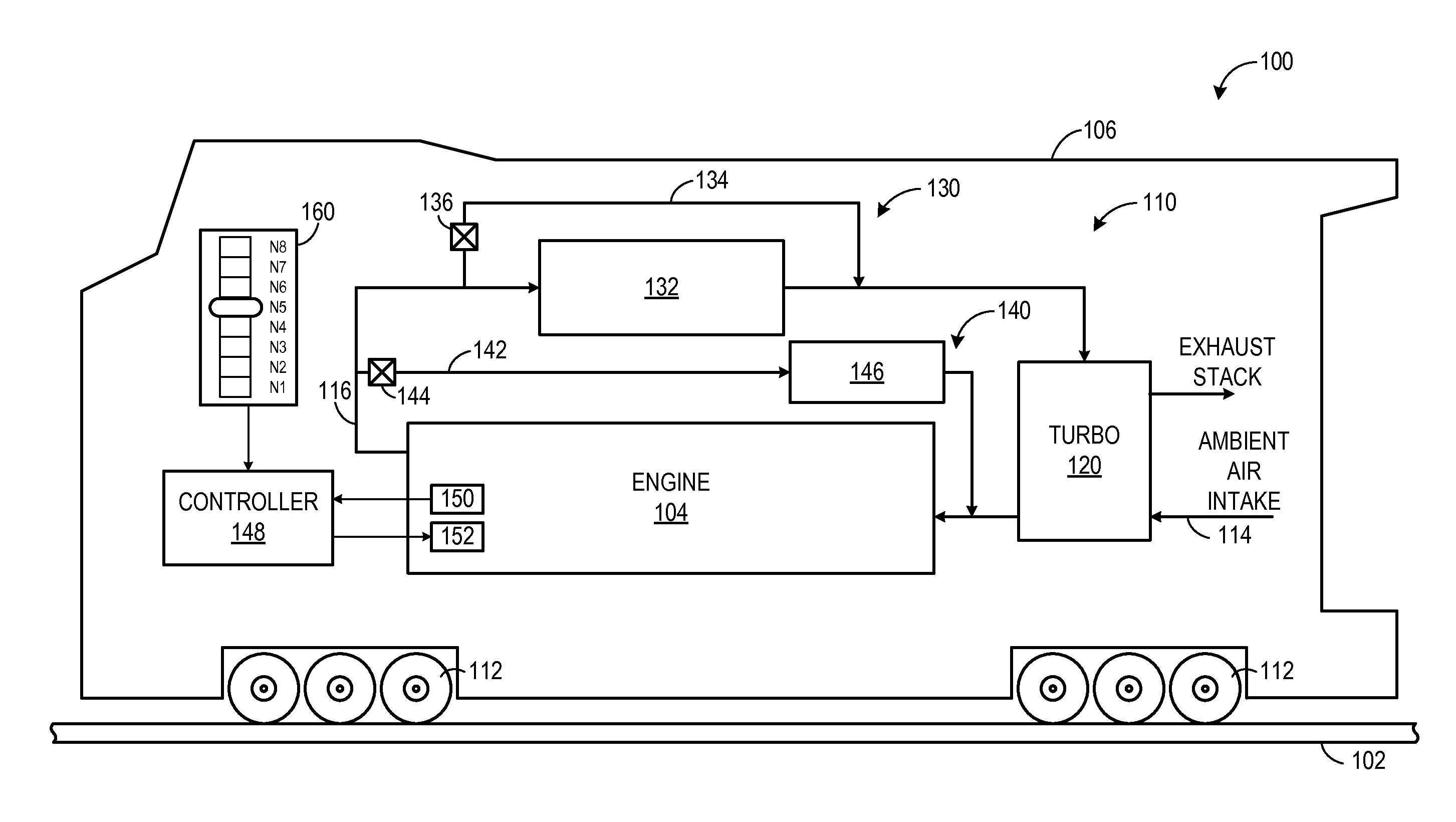
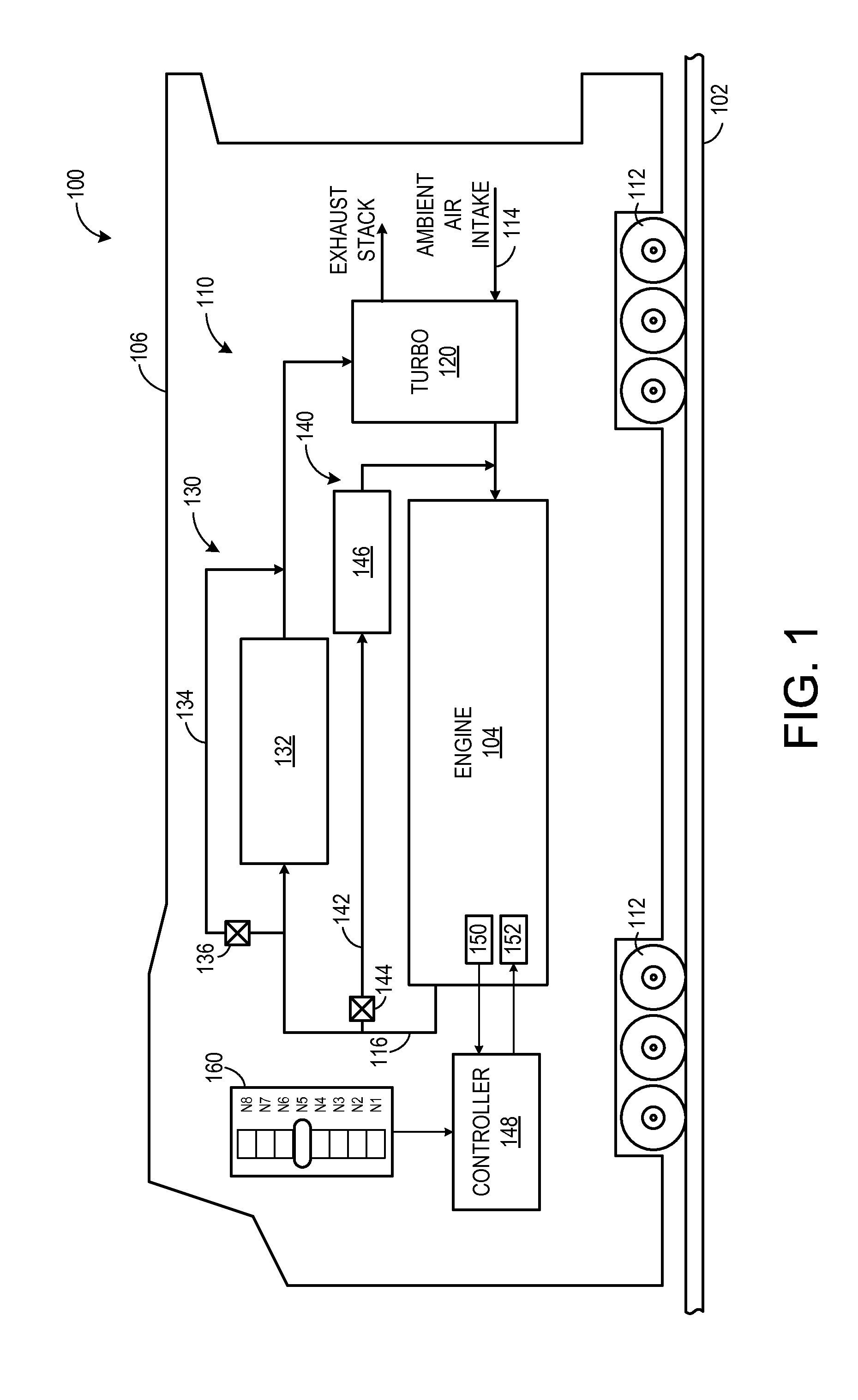
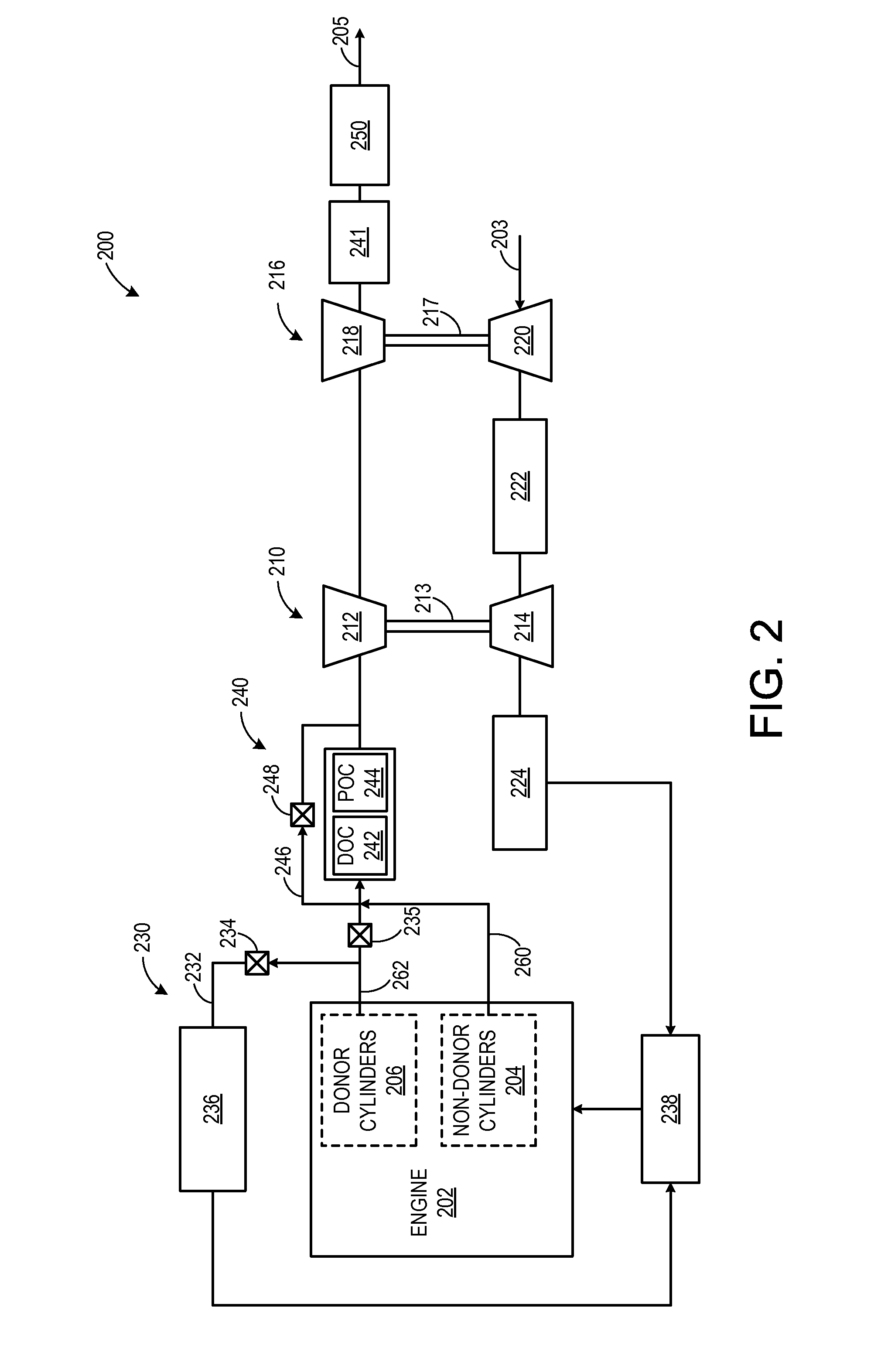
[0017]The following description relates to various embodiments of methods and systems for controlling emissions from an engine. In one example embodiment, a system for an engine includes an exhaust passage through which exhaust gas flows from the engine, a turbocharger with a turbine positioned in the exhaust passage, and an exhaust gas treatment system disposed in the exhaust passage upstream of the turbocharger, the exhaust gas treatment system including a diesel oxidation catalyst and a particulate oxidation catalyst and a bypass with a bypass valve. The system further includes a controller configured to identify or detect a transient engine operating condition and, in response to the transient engine operating condition, adjust the bypass valve to reduce exhaust flow through the exhaust gas treatment system. In one example, exhaust gas flow through the exhaust gas treatment device may be reduced during transient conditions by opening the valve. Thus, the exhaust gas flow may byp...


PUM


Abstract

Methods and systems for an engine are provided. In one example, a system for an engine comprises an exhaust passage through which exhaust gas is configured to flow from the engine, a turbocharger with a turbine positioned in the exhaust passage, an exhaust gas treatment system disposed in the exhaust passage upstream of the turbine and including at least one exhaust gas treatment device and a bypass with a bypass valve, the bypass valve configured to be adjusted to reduce exhaust gas flow through the exhaust gas treatment system in response to a transient engine operating condition, and an exhaust gas recirculation system coupled between the exhaust passage and an intake passage of the engine, the exhaust gas recirculation system including an exhaust gas recirculation passage and at least one exhaust gas recirculation valve, an inlet of the exhaust gas recirculation system positioned upstream of the exhaust gas treatment system.

Description

RELATED APPLICATIONS[0001]This application is a continuation-in-part from U.S. patent application Ser. No. 13 / 152,361, entitled SYSTEMS AND METHODS FOR AN ENGINE, filed Jun. 3, 2011, which is hereby incorporated in its entirety herein by reference for all purposes.FIELD[0002]Embodiments of the subject matter disclosed herein relate to systems and methods for an engine with an exhaust gas treatment device.BACKGROUND[0003]During operation, internal combustion engines generate various combustion by-products that are emitted from the engine in an exhaust stream. As such, various approaches may be utilized in order to reduce regulated emissions. In some examples, nitrogen oxide (NOx) emissions may be reduced by employing exhaust gas recirculation (EGR), carrying out combustion in the engine with a Miller cycle, and / or including an exhaust gas treatment system with a device such as a NOx trap in an exhaust passage of the engine.[0004]In other examples, the inventors herein have recognized...

Claims


Application Information

Patent Timeline
Patent Type & Authority Applications(United States)
IPC IPC(8): F02B37/18
CPCF02B37/183B61C5/04F01N3/021F01N3/10F01N3/103F01N3/2053F01N9/00F01N13/0097F01N2410/00F01N2410/10F01N2900/08F02B37/00F02B37/013F02B37/12F02B37/20F02B39/16F02D13/0269F02D19/0647F02D19/0692F02D41/0007F02D41/0025F02D41/0055F02D41/0235F02D41/10F02D2041/0265F02D2200/0414F02D2200/0802F02D2200/602F02M26/05F02M26/43Y02T10/12Y02T10/30Y02T10/40
Inventor GOKHALE, MANOJ
Owner GE GLOBAL SOURCING LLC
Why Eureka
Try Eureka