
Bulk Wireless Charger

a wireless charger and battery pack technology, applied in the direction of transportation and packaging, arrangements for several simultaneous batteries, indicating/monitoring circuits, etc., can solve the problems of limiting battery life, significant time and effort, and the connector used for connecting the charger to the device itself being subject to reliability issues, etc., to achieve the effect of convenient compact arrangemen

Inactive Publication Date: 2015-11-12
YOUNG CHRIS M
View PDF3 Cites 42 Cited by
  • Summary
  • Abstract
  • Description
  • Claims
  • Application Information

AI Technical Summary

Benefits of technology

The patent describes an improved bulk wireless charger station that can charge multiple electronic devices by reorienting the charging devices to be placed in parallel with each other instead of being placed in a coplanar manner. The charging station includes an enclosure with a slot for holding devices, and a wireless charger transmitter that charges the device using an inductive charging method. The wireless charger transmitter is shielded to prevent interfacing with wireless charging receivers outside the slot. The charging station can also communicate with the device and host computer through high-frequency communications, and may include alignment stops to align the device with the wireless charger transmitter when placed in the slot. Overall, the charging station provides a compact and efficient way to charge multiple electronic devices.

Problems solved by technology

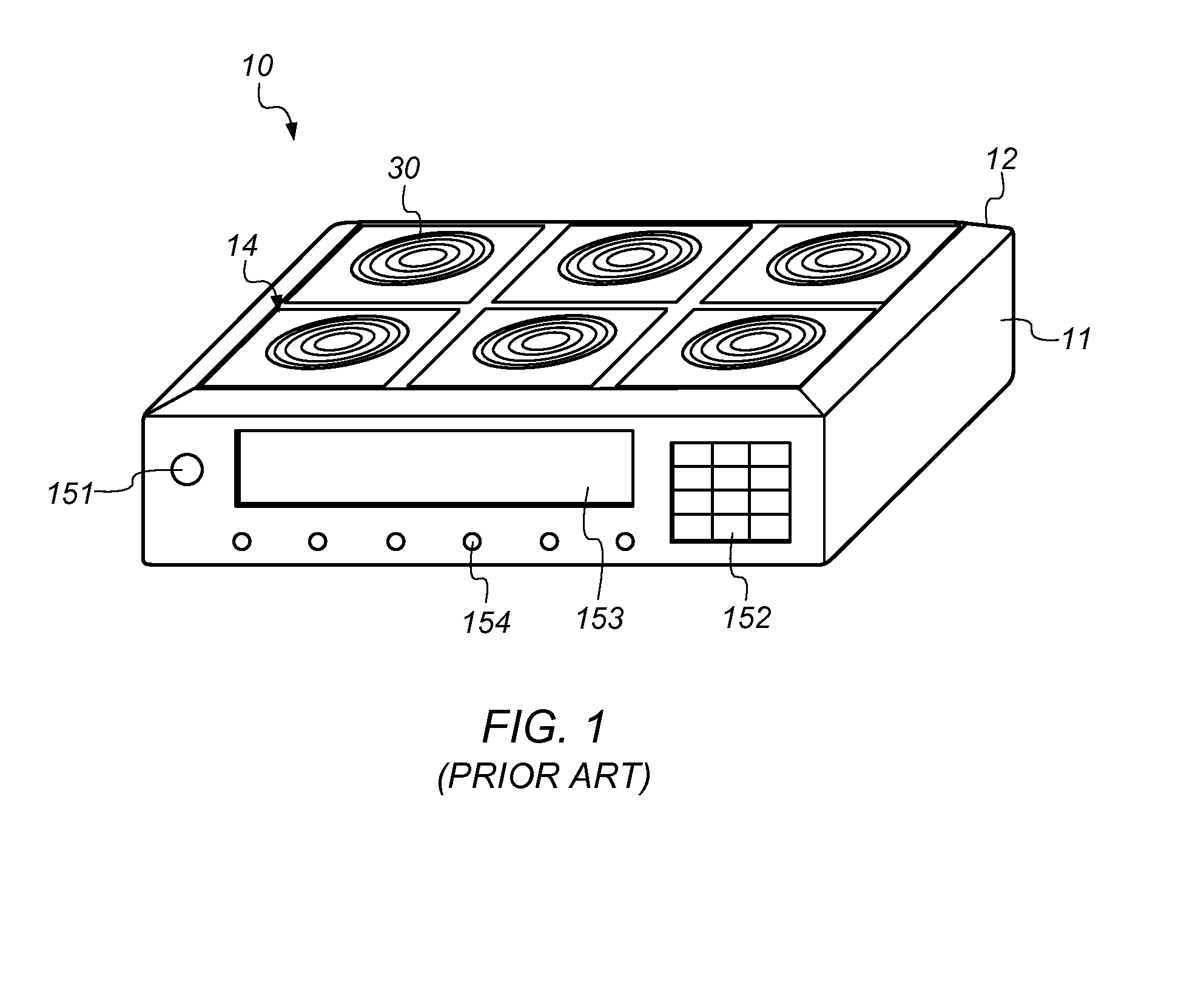
Portable smart computing devices such as smart phones, tablets and ultra-notebook computers are typically required to be lightweight, yet they are still expected to satisfy significant computing demands which can limit battery life.
In situations where bulk charging of multiple devices is required, connecting charging cables to the devices can result in significant time and effort.
In addition, the connector used for connecting the charger to the device can itself be subject to reliability issues with its fragile pins and repetitively flexed cable.
Such a large area is inconvenient for many locations and does not scale favorably.

Method used


Image

  • Bulk Wireless Charger
  • Bulk Wireless Charger
  • Bulk Wireless Charger

Examples


Embodiment Construction

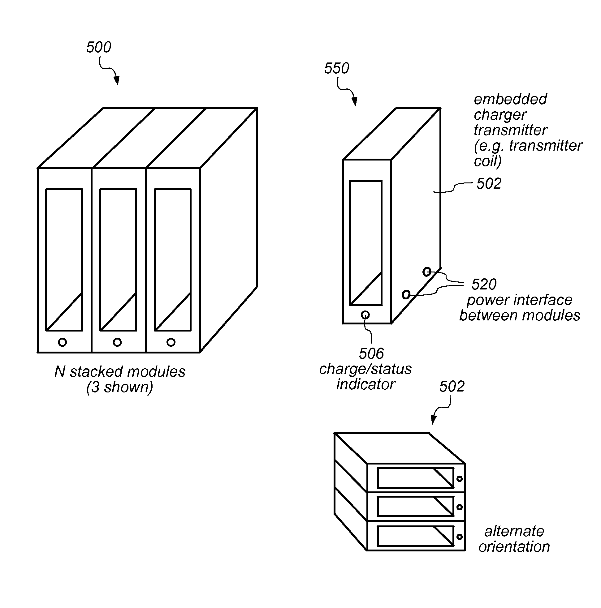
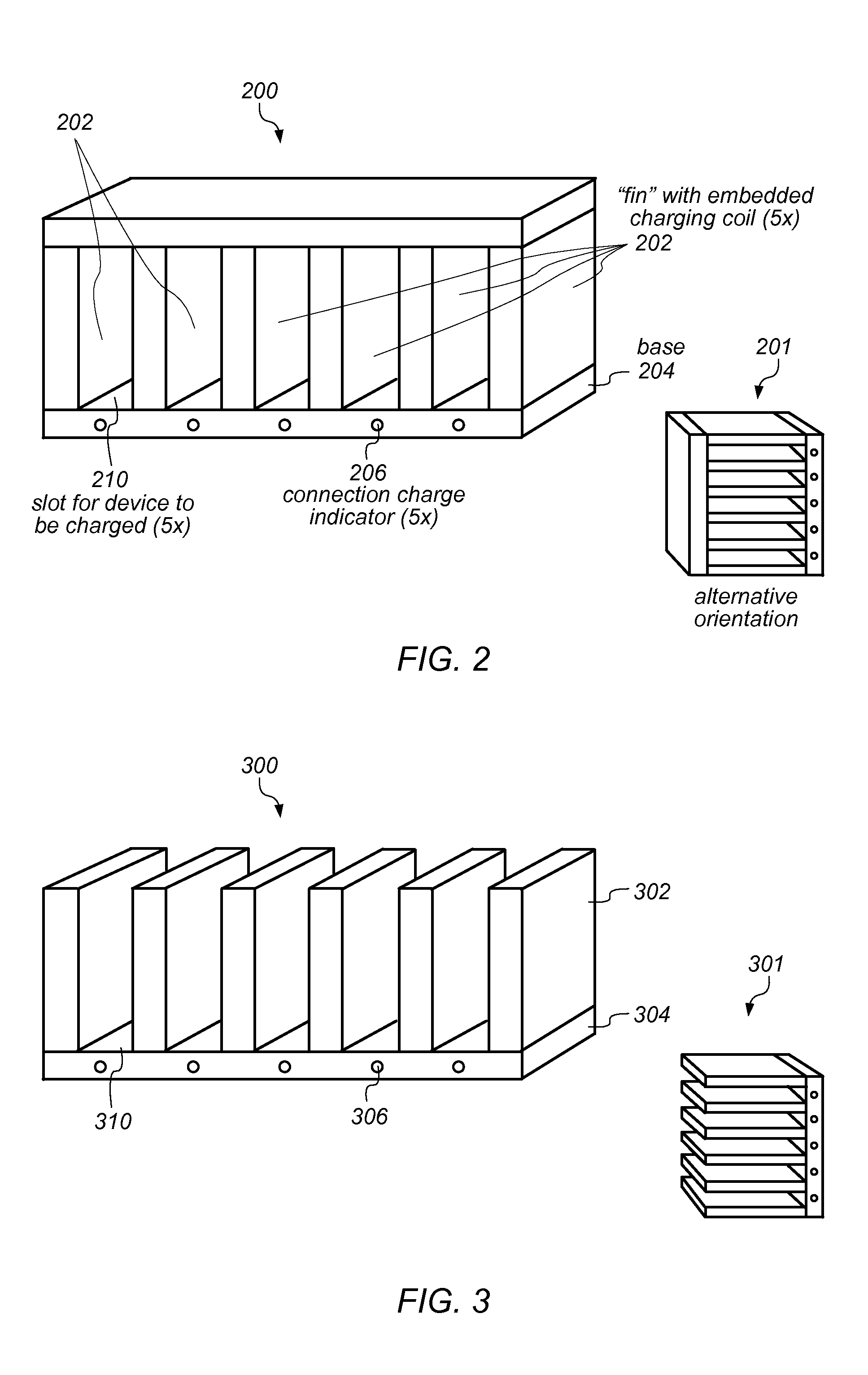
[0019]As an improvement upon existing bulk wireless charging methods and systems, various embodiments are disclosed herein of wireless bulk charger stations in which the devices to be charged (i.e. the charging devices) are reoriented such that the charging devices are parallel to each other as opposed to being disposed in a coplanar manner. Such arrangement permits multiple devices to be simultaneously charged in a wireless manner without requiring ever increasing surface area for the wireless charging system.

[0020]In various embodiments, a bulk wireless charger station or charger system may allow the charging devices to be stacked on top of each other with the main surfaces of the charging devices parallel to each other, or the charging devices placed side by side with their main surfaces aligned vertically and in parallel. Each device to be charged (i.e. each charging device) may have an embedded inductive charger receiving apparatus enabling the device to be charged. Furthermore...


PUM


Abstract

An improved bulk wireless charger station may be constructed of a number of individual wireless charger modules. Each module may include an embedded wireless charger transmitter with the capability of wirelessly charging a device inserted into the module. The device may have the capability of being wirelessly charged via a wireless charging receiver in communication with the wireless charger transmitter. Charging the device may include charging a battery or other electrical storage element within the device, which, once charged, may power the device during use. The charger modules may be stackable horizontally and / or vertically to form the charger station. Each charger module may also include a power interface for receiving power from either a power base or other charger modules, and / or a communication interface for communicating with other charger modules and / or control station(s). The embedded wireless charger transmitter may be a transmitter coil controlled through a power conversion / control board.

Description

PRIORITY CLAIM[0001]This application claims benefit of priority of U.S. Provisional Patent Application Ser. No. 61 / 990,394 titled “Bulk Wireless Charger”, filed on May 8, 2014, which is hereby incorporated by reference as though fully and completely set forth herein.FIELD OF THE INVENTION[0002]The present invention relates to the field of electrical charging devices, and more particularly to the design of an improved bulk wireless charger.DESCRIPTION OF THE RELATED ART[0003]Portable smart computing devices such as smart phones, tablets and ultra-notebook computers are typically required to be lightweight, yet they are still expected to satisfy significant computing demands which can limit battery life. These devices have been joined in recent years by wearable devices such as smart glasses and smart watches. Conventional charging of the batteries in such portable (or wearable) computing devices and mobile devices is typically accomplished through the use of an adapter with a chargin...

Claims


Application Information

Patent Timeline
Patent Type & Authority Applications(United States)
IPC IPC(8): H02J7/02H02J7/00
CPCH02J7/025H02J7/0042H02J2007/0049H02J7/007H02J7/0021H02J7/0047H02J7/0044H02J50/90H02J50/80H02J7/0049H02J50/402H02J7/0013H02J50/10H02J50/70
Inventor YOUNG, CHRIS M.
Owner YOUNG CHRIS M
Learn More