Marking device

Inactive Publication Date: 2006-04-04
EDWARD PRYOR & SONS
View PDF9 Cites 4 Cited by
  • Summary
  • Abstract
  • Description
  • Claims
  • Application Information

AI Technical Summary

Benefits of technology

[0015]The clamshells may be moulded from plastics material, in which event there will inevitably exist some tolerance in the dimensions of the clamshell when mated together. Accordingly, a disc spring is preferably disposed on at least one pin between the housing and the frame to take up any tolerance between the housing and frame. The disc spring is compressed when the clam shells are first assembled and holds the frame in a specific position. This is done without greatly increasing the frictional engagement between the frame and the housing, at least not to such an extent that the frame is clamped by the housing. There is thus no need for

Problems solved by technology

U.S. Pat. No. 6,135,022 addresses some of these issues but nevertheless fails to provide a design of device which is either easy to

Method used


Image

  • Marking device
  • Marking device
  • Marking device

Examples


Embodiment Construction

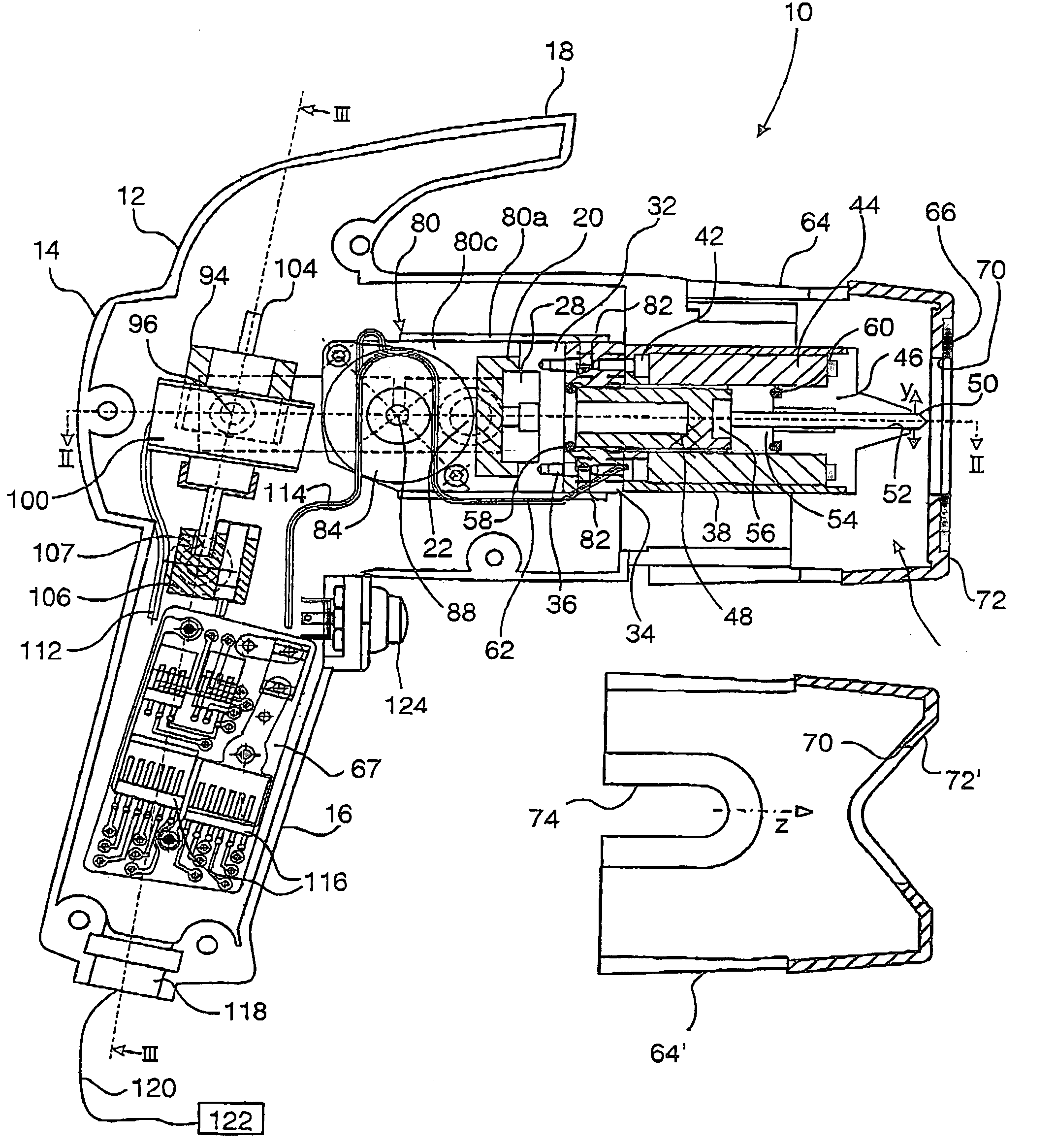
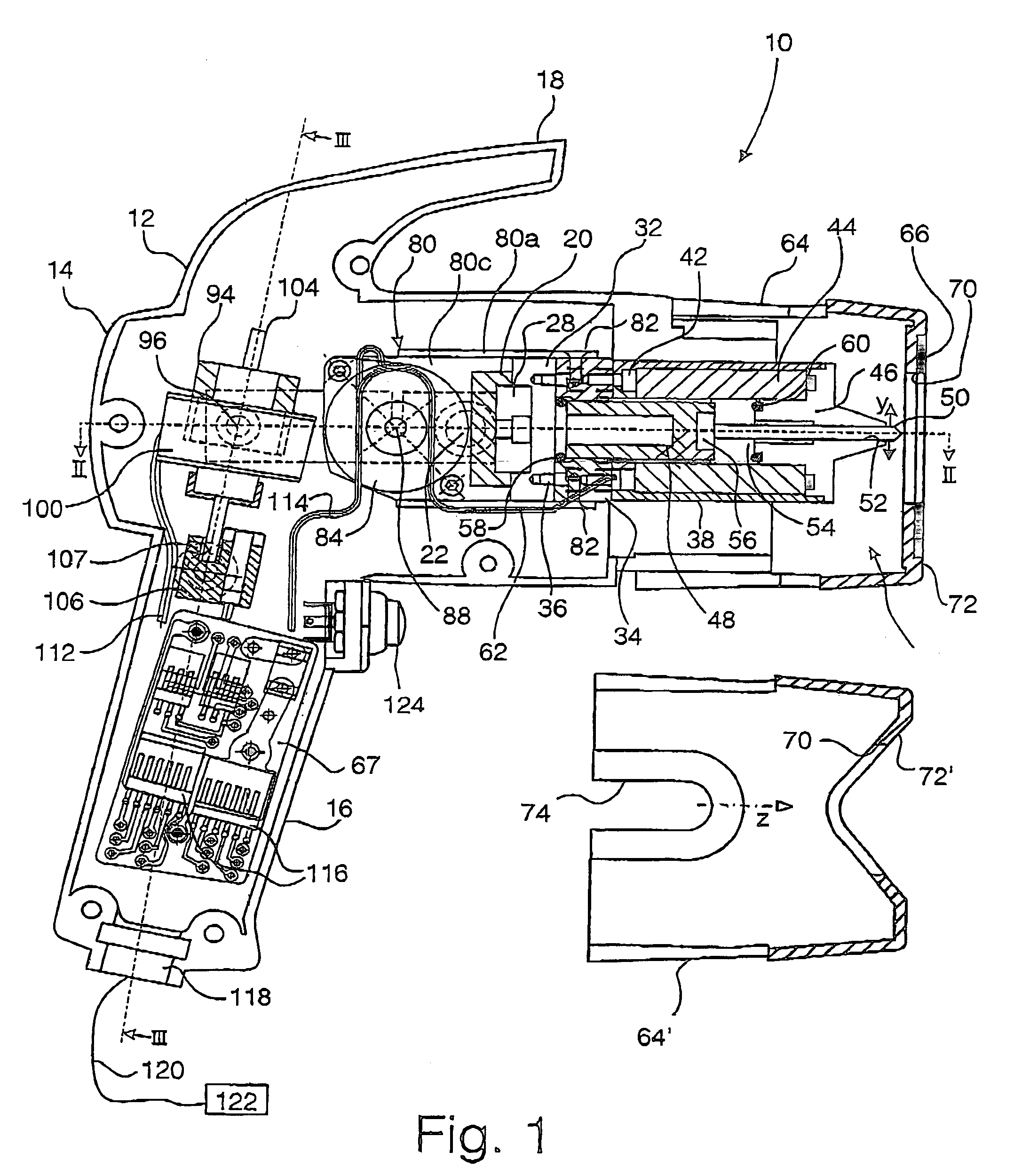
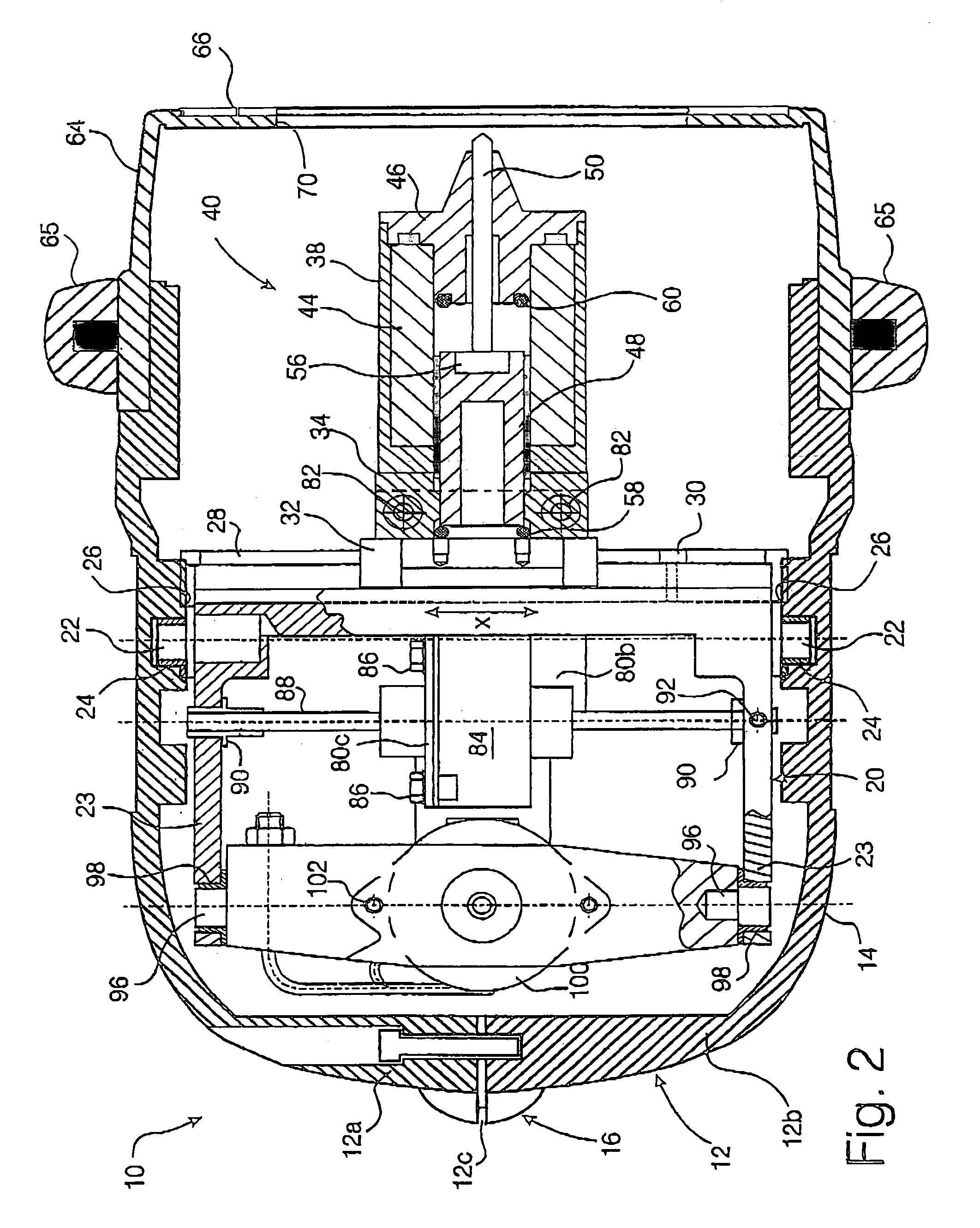
[0053]Referring to the drawings, a marking device 10 comprises a plastics housing 12 comprising two clamshell halves 12a,b joined at a centre line 12c extending around the entire periphery of the device 10. The clamshell halves are connected together by screws (not shown) and define a main body 14, a pistol grip handle 16 and a top steady handle 18.

[0054]In the body 14 is pivotally disposed a frame 20 comprising two pivot pins 22 received in bushings 24 fitted into the housing 12. To permit variation in the dimensional precision of the clamshell housing 12 when mated together, a disc spring 26 is disposed between each pivot pin 22 and its corresponding bearing bush 24. The disc spring 26 serves to centralise the frame 20 within the housing body 14 and take up any loose play between them.

[0055]The frame 20 is essentially U-shaped, along the base 21 of which is fixed a rail 28 by machine screws 30 (see FIG. 4). Slideably carried in a first, x, direction on the rail 28 is a carriage 32...


PUM


Abstract

A marking device (10) comprises a housing (12) having a handle (16). A frame (20) is pivotally mounted in the housing aout a first axis (22). A marking head (40) mounted on the frame for translational movement in the frame by a first motor (84) in a first direction (x) parallel said first axis and spaced therefrom. A second motor (100) is arranged to pivot the frame with respect to the housing about said first axis in a second, substantially orthogonal direction (y). The pin moves in a third orthogonal direction (z). The motors (84, 100) are disposed within the confines of the frame (20) and move on fixed screws (84, 104).

Description

FIELD OF THE INVENTION[0001]This invention relates to a marking device, particularly for metal surfaces by impacted dot formation for permanent identification purposes.BACKGROUND[0002]In the automotive and aerospace industries (especially), it is more and more frequently desired to mark permanently different components of a vehicle in the course of its manufacture. Moreover, it is desired to mark pieces after assembly in the vehicle to ensure each is marked with the relevant markings for the vehicle in question. Thus, rather than marking individual components in a fixed marking machine, the desire now is to mark the components in situ with a portable, handheld marking device.[0003]On the other hand, with the advent of machine readable codes, precise marking is of significant importance. There is a need therefore to combine the conflicting requirements of lightness and compactness of a handheld marking device with the precision and robustness that impact marking needs in order to be ...

Claims


Application Information

Patent Timeline
IPC IPC(8): B41J2/22B44B3/00
CPCB44B3/005B41J2/22
Inventor LUNN, ALAN JOHN
Owner EDWARD PRYOR & SONS
Why Eureka
Try Eureka