
Object positioning method

a positioning method and object technology, applied in the direction of transportation and packaging, transportation items, packaging, etc., can solve the problems of incorrect fill level indication in conventional measurement devices, difficulty in dimensionally manufacturing of fuel tanks, and inability to indicate the correct fuel level of position, so as to improve the management of fuel refilling.

Inactive Publication Date: 2015-11-19
FORD GLOBAL TECH LLC
View PDF6 Cites 4 Cited by
  • Summary
  • Abstract
  • Description
  • Claims
  • Application Information

AI Technical Summary

Benefits of technology

The patent describes a system for accurately measuring the level of fuel in a vehicle's combustion engine. This is important for managing fuel refilling during operation. The system includes support domes on the bottom of the fuel tank that help position the fuel delivery module, while preventing the pump from touching the tank. This reduces the chance of surface irregularities affecting the position of the fuel delivery module. Overall, the system improves the accuracy of fuel level readings and makes it easier for operators to manage fuel refilling.

Problems solved by technology

However, in cases where the fuel level measurement module is not in the calibrated position, or orientation, the arm position may not indicate the correct fuel level based on the shape knowledge of the fuel tank.
US 2012 / 0234074 A1 titled “Measurement device and method for determining a fluid fill level in a fuel tank”; the tilting of components of the measurement device may cause incorrect fill level indications in conventional measurement devices.
Fuel tanks are dimensionally challenging to manufacture.
The typical methods of controlling the parralellism of the internal bottom surface of the fuel tank, however, often fail to produce desirable results, potentially leading to unintended, or inaccurate, fuel level indication information being presented to the driver of the vehicle.

Method used


Image

  • Object positioning method
  • Object positioning method
  • Object positioning method

Examples


Embodiment Construction

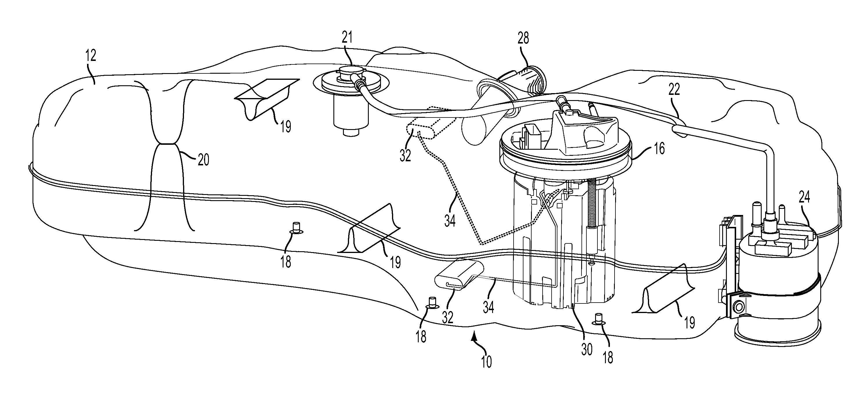
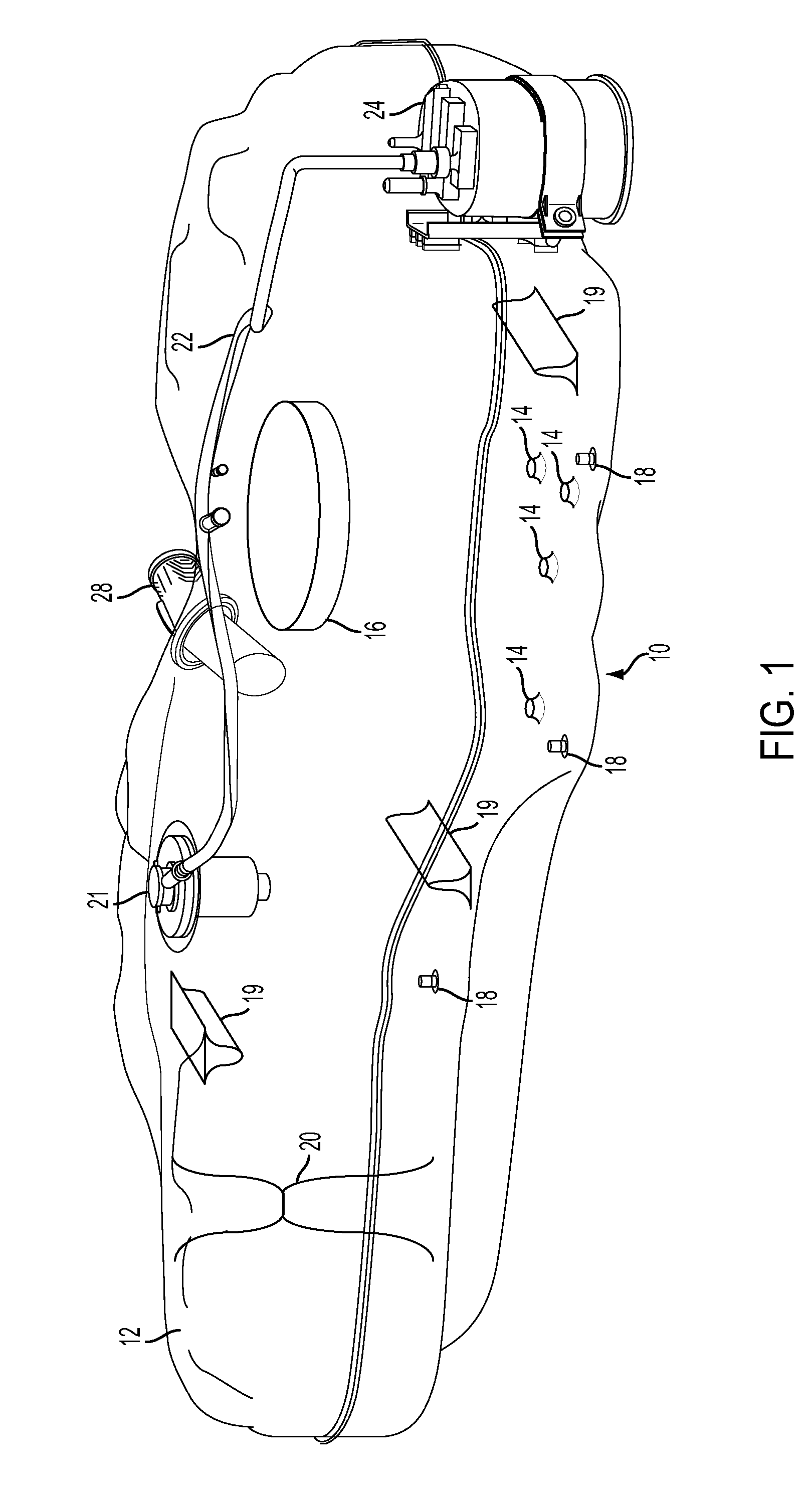
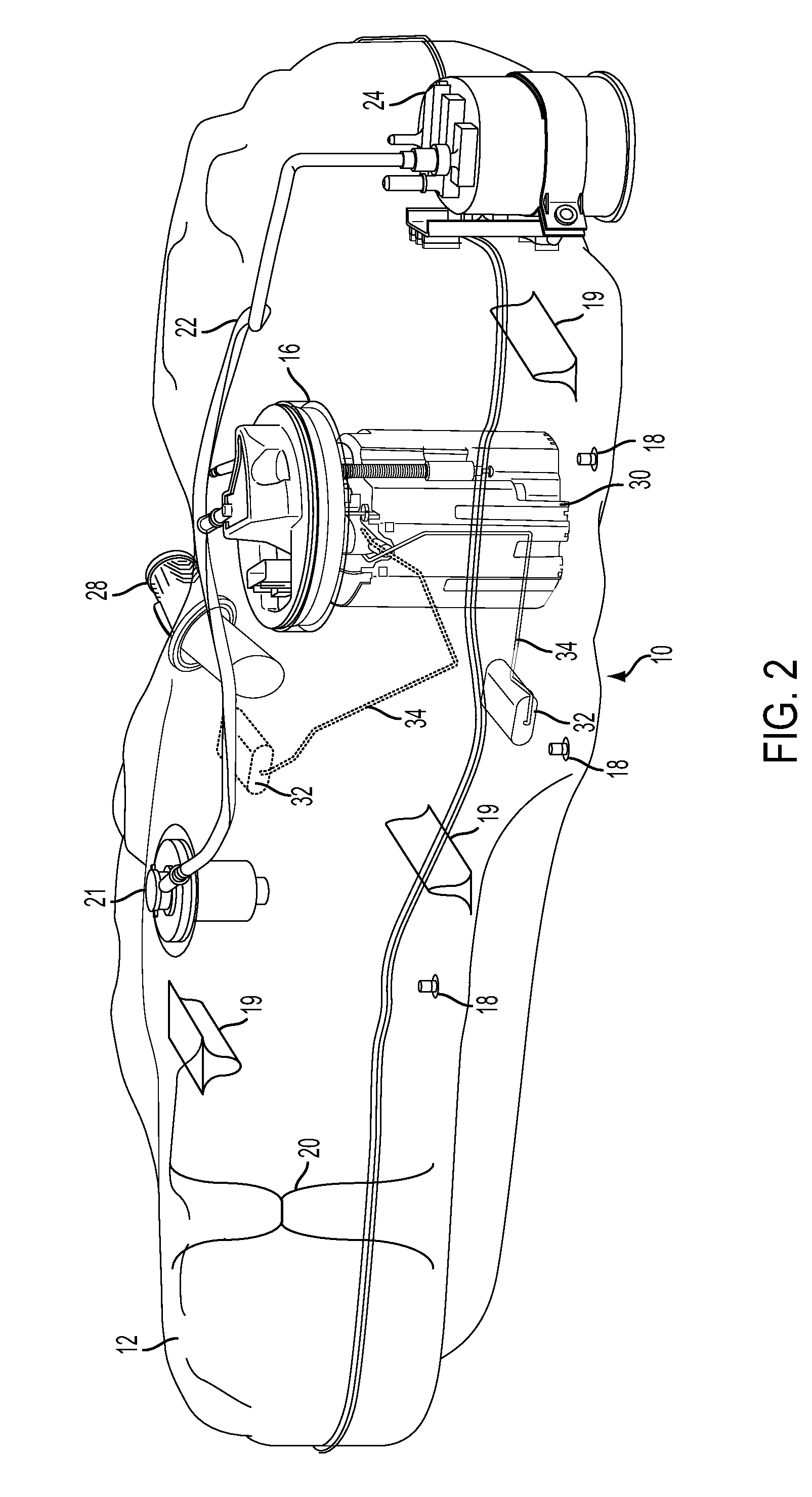
[0015]The following description relates to systems and methods for a fuel tank configured with support domes on the bottom surface used to engage with a fuel tank insert, such as a fuel delivery module that includes fuel level measurement components, fuel pump, and various other components. The support domes are configured to provide accurate locating points to provide more consistent fuel level sensing, while preventing the fuel delivery module from contacting the bottom surface of the fuel tank. Such an approach reduces potential for surface irregularities of the bottom surface from influencing the position and / or orientation of the fuel delivery module.

[0016]Turning now to the figures, FIGS. 1 and 2 show therein side views 10 of example fuel tank 12, where FIG. 1 shows fuel tank 12 including an example of support domes 14 and FIG. 2 shows fuel delivery module 16 installed within fuel tank 12. The fuel tank may be formed of plastic that is molded into shape, for example blow molde...


PUM


Abstract

A fuel tank having one or more support domes configured to engage with, and assist in positioning, a fuel tank insert.

Description

BACKGROUND AND SUMMARY[0001]Vehicles using combustion engines include a manufactured vessel (e.g., a blow molded fuel tank) to hold the fuel used to fuel engine combustion. Accurate fuel level readings enable a vehicle operator to better manage fuel refilling during vehicle operation.[0002]In order to collect fuel level information, fuel tanks may use a float attached to an arm, where a fuel level measurement module can determine the volume of fuel remaining by the position of the arm and calibrated knowledge of the shape of the fuel tank. However, in cases where the fuel level measurement module is not in the calibrated position, or orientation, the arm position may not indicate the correct fuel level based on the shape knowledge of the fuel tank. Specifically, as taught in US Patent Application Publication No. US 2012 / 0234074 A1 titled “Measurement device and method for determining a fluid fill level in a fuel tank”; the tilting of components of the measurement device may cause in...

Claims


Application Information

Patent Timeline
Patent Type & Authority Applications(United States)
IPC IPC(8): B60K15/077
CPCB60K15/077B60K2015/0772B60K2015/0344B60K15/03B60K2015/03453B60K15/03177
Inventor CRAGEL, DANIEL FRANKHIPP, MARK EDWARD
Owner FORD GLOBAL TECH LLC
Learn More