Decommissioning offshore oil and gas wells

a technology for offshore oil and gas wells and wells, which is applied in the direction of drilling pipes, wellbore/well accessories, floating buildings, etc., can solve the problems of requiring a lot of resources, requiring a lot of time, and the time of a jack-up or modular rig is very expensive at several hundred thousand dollars per day, so as to achieve the effect of greatly reducing the footprint of the platform

Active Publication Date: 2015-11-19
CONOCOPHILLIPS CO
View PDF10 Cites 12 Cited by
  • Summary
  • Abstract
  • Description
  • Claims
  • Application Information

AI Technical Summary

Benefits of technology

[0009]The first and / or second rig towers may be capable of supporting heavy decommissioning equipment, for example for plug and abandon operations. The equipment may for example be milling equipment capable of milling a 10 meter length of, e.g. 12¼ inch well casing. This kind of heavy equipment requires a lot of resources such as mud and power. Supplying these resources to the second well tower on the platform from the jack up rig means that there may be no need for a large modular rig on the platform having the capability to supply these requirements; hence the footprint on the platform may be greatly reduced, allowing simultaneous decommissioning operations to be conducted in two wells simultaneously. This may include simultaneous heavy operations such as milling a long length (>10 m) or large diameter (e.g. 12¼ inch) well casing.
[0010]The time taken to perform any two decommissioning operations may vary considerably from e.g. a few days to as much as 120 days, the average time being 50-60 days. A great advantage of the method described above is that the first or second rig tower may be moved and a new operation commenced in a different well, whilst the other rig tower is still operating.

Problems solved by technology

Rig time for a jack up or modular rig is very expensive at several hundred thousand dollars per day, and decommissioning a platform with e.g. 40 wells where each job takes 50-60 days is clearly a very time consuming process, taking a number of years to finish.
This kind of heavy equipment requires a lot of resources such as mud and power.

Method used


Image

  • Decommissioning offshore oil and gas wells
  • Decommissioning offshore oil and gas wells

Examples


Embodiment Construction

[0016]Turning now to the detailed description of the preferred arrangement or arrangements of the present invention, it should be understood that the inventive features and concepts may be manifested in other arrangements and that the scope of the invention is not limited to the embodiments described or illustrated. The scope of the invention is intended only to be limited by the scope of the claims that follow.

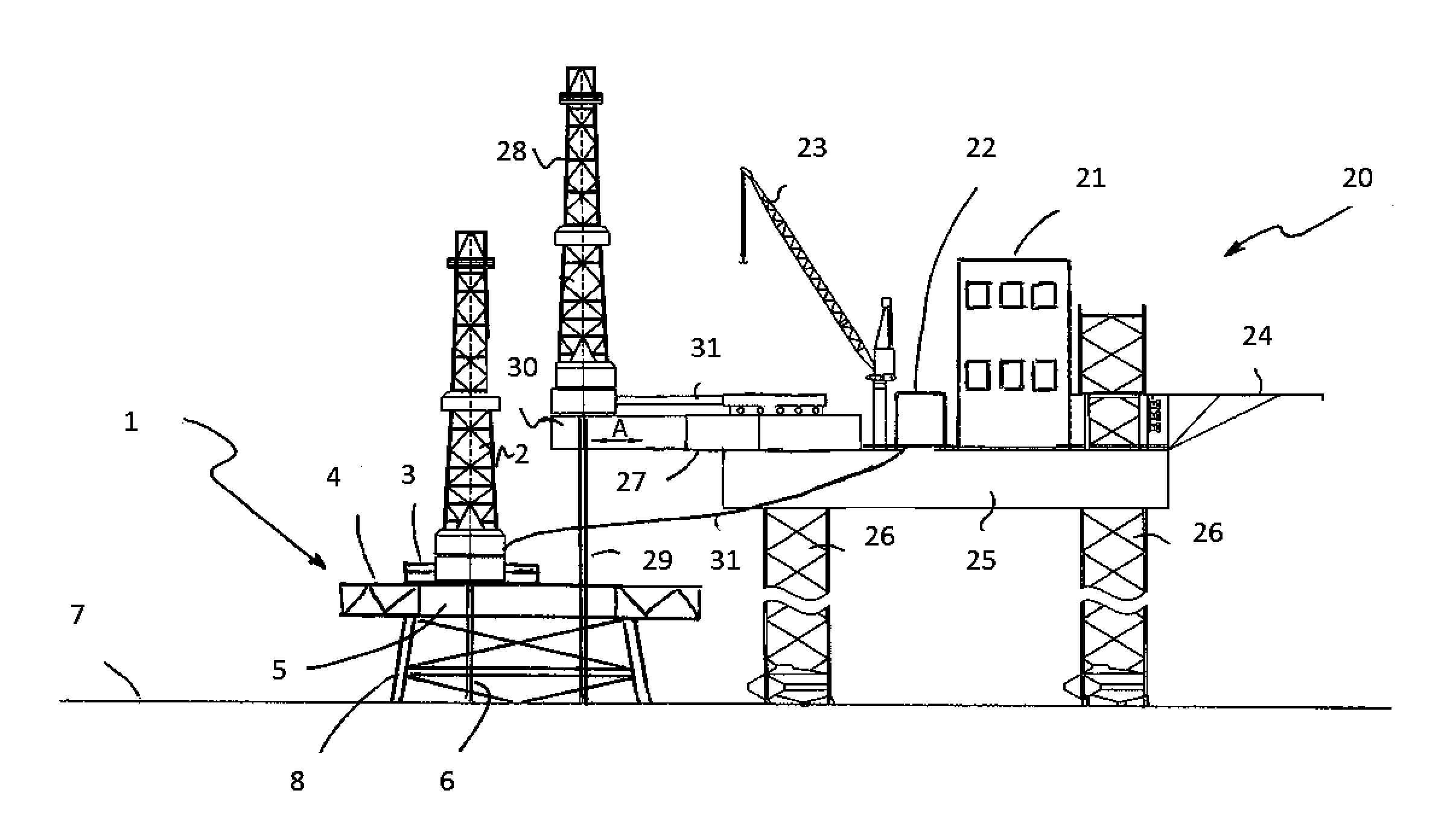
[0017]As shown in FIG. 1, an oil and / or gas platform 1 has had most of its installations connected with production stripped off its deck 4, and in their place is installed a large decommissioning rig tower 2 capable of operating with the heavy milling machinery often required for plug and abandon operations.

[0018]The platform decommissioning rig tower 2 is mounted on skids 3 which allow it to be moved in the X-Y plane (parallel to the surface of the deck 4) across all or part of the well bay 5. A work string 6 is shown descending from the rig tower 2, through the well bay 5 a...


PUM


Abstract

Method and structures perform decommissioning of offshore oil and gas platforms with associated wells. By installing on a platform (1) a movable decommissioning rig tower (2) but stripping away most of the other structures and equipment on the platform (1), and specifically not providing supporting resources such as drilling mud and power, accommodation, etc. on the platform, it is possible for both the rig tower (2) and a further rig tower (28) installed on a jack up rig (20) located alongside the platform (1) to access the well bay (5) of the platform. Thereby, two wells may be accessed simultaneously through the same well bay (5) and respective decommissioning operations carried out simultaneously and independently.

Description

CROSS-REFERENCE TO RELATED APPLICATIONS[0001]This application is a non-provisional application which claims benefit under 35 USC §119(e) to U.S. Provisional Application Ser. No. 62 / 000,345 filed May 19, 2014, entitled “DECOMMISSIONING OFFSHORE OIL AND GAS WELLS,” which is incorporated herein in its entirety.FIELD OF THE INVENTION[0002]This invention relates to the decommissioning of offshore oil and gas wells, involving, e.g., time consuming plug and abandon operations, using heavy milling equipment, in a large number of wells normally accessed from the well bay of an offshore platform.BACKGROUND OF THE INVENTION[0003]After the end of their useful life, offshore oil and gas wells need to be safely taken out of service and plugged permanently. In a group of wells associated with a given offshore platform, some may come to the end of their economic life and may be plugged, perhaps with a temporary plug. There will come a time, though, where an entire platform and its associated wells ...

Claims


Application Information

Patent Timeline
Patent Type & Authority Applications(United States)
IPC IPC(8): E02B17/00B63B35/44E21B19/16E21B15/02E21B19/00
CPCE02B17/00E21B15/02E21B19/002E02B2017/0095E02B17/0034B63B35/44E02B2017/0052E21B19/16E21B15/003E21B29/00
Inventor GARDER, JEAN
Owner CONOCOPHILLIPS CO
Why Eureka
Try Eureka