Steam conditioning system

a technology of steam conditioning and steam generator, which is applied in the direction of heat exchange equipment safety devices, machines/engines, light and heating equipment, etc., can solve the problems of insufficient time for proper mixing and evaporation, insufficient effective distance of desuperheating stations, and insufficient sound inside the condenser, etc., to increase the effective distance of the desuperheating station, increase the residence time, and save valuable space in the power plan

Active Publication Date: 2015-11-19
HOLTEC INT
View PDF2 Cites 10 Cited by
  • Summary
  • Abstract
  • Description
  • Claims
  • Application Information

AI Technical Summary

Benefits of technology

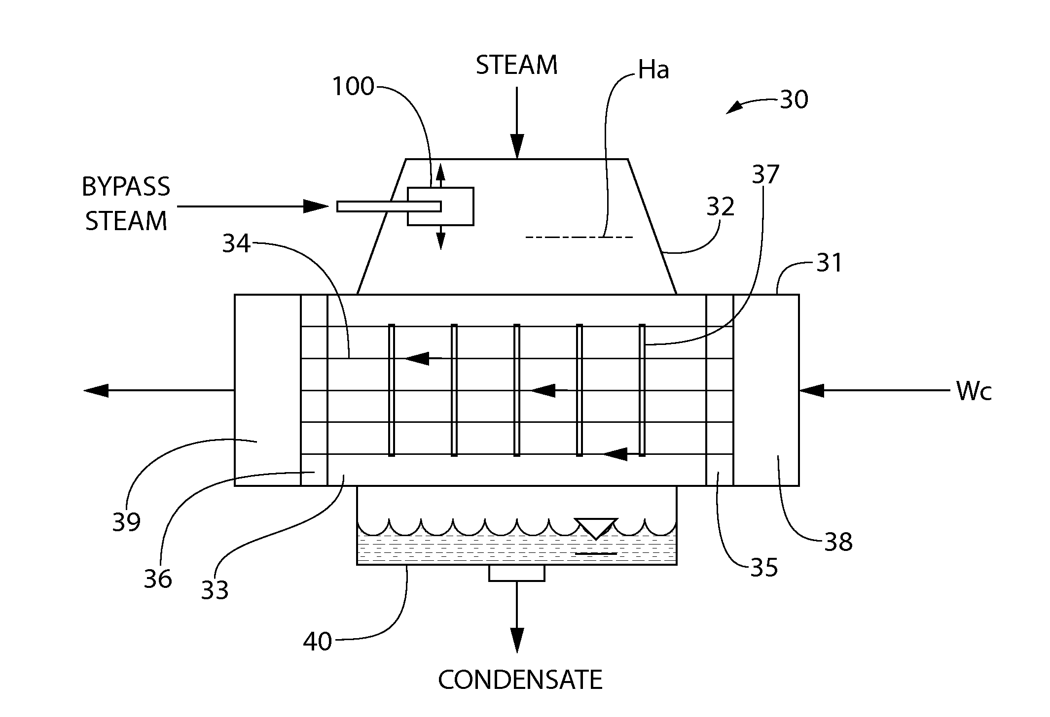
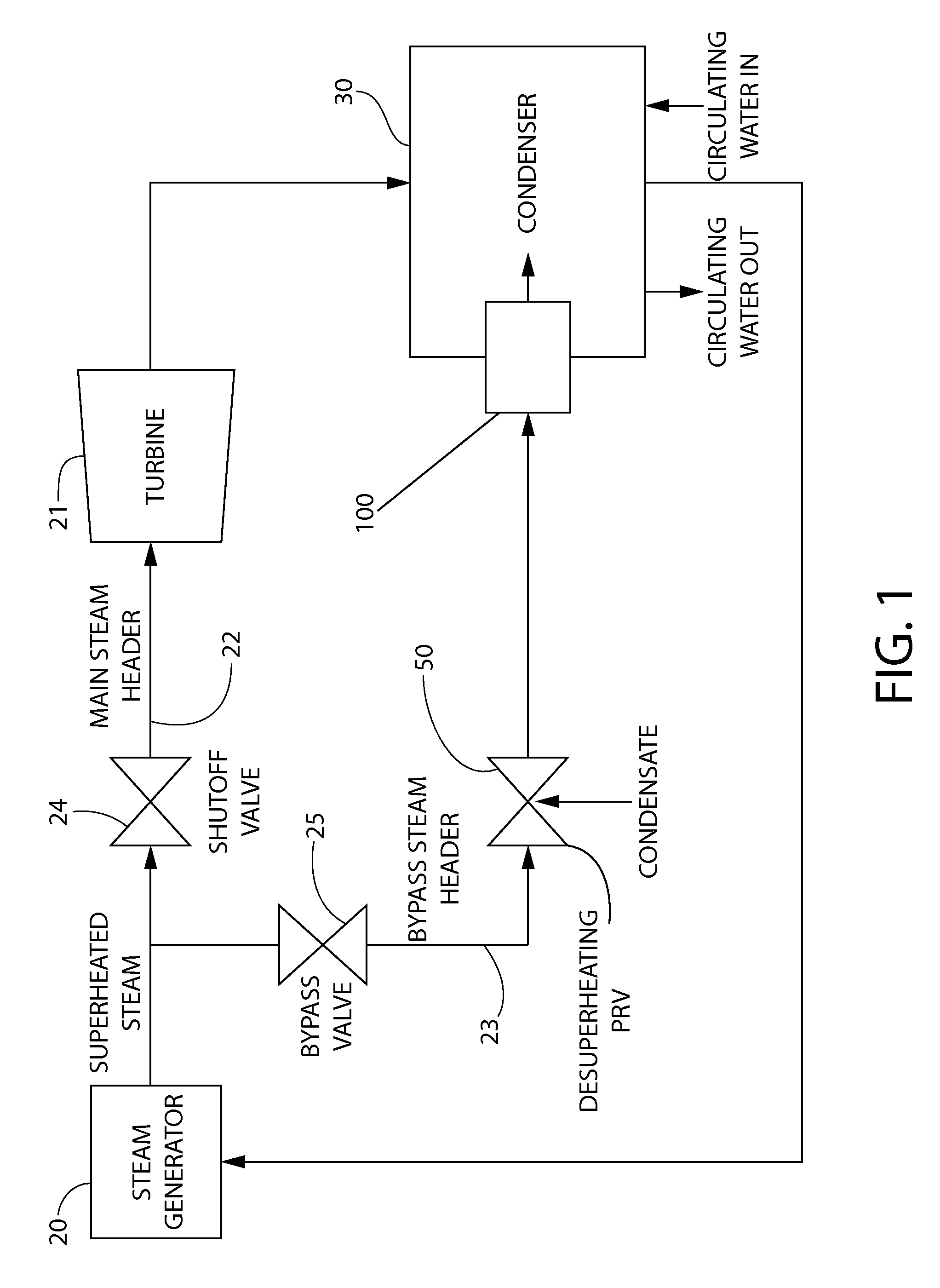
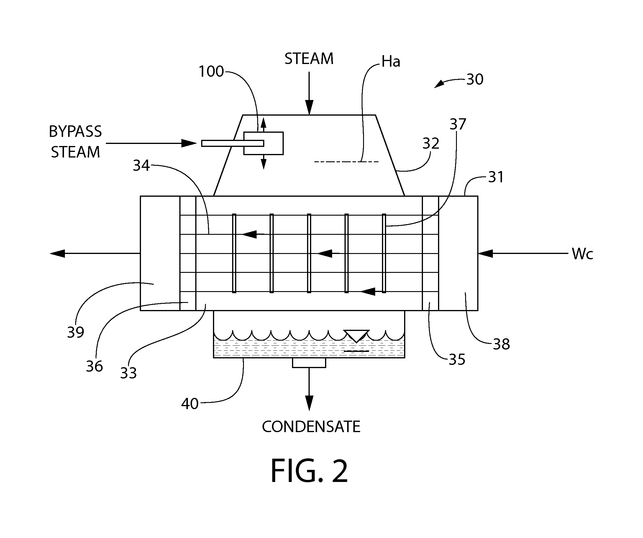
[0009]A novel approach to designing a steam conditioning device useable in a bypass steam application is provided that increases the effective distance of the desuperheating station from the point of exit into the condenser neck or dome by incorporating an integral evaporative core within the bypass header. The bypass steam conditioning device is configured to increase the residence time of the desuperheated steam flow to allow for total or near total evaporation of any entrained water droplets within a relatively short length of piping. Advantageously, this allows the length of bypass steam header piping between the desuperheating and pressure-reducing station and condenser to be minimized, thereby conserving valuable space within the power plant.

Problems solved by technology

This causes steam to exit at sonic conditions inside the condenser.
A small carryover of water droplets that have not had time to evaporate in the surrounding superheated steam can cause significant damage to the condenser internals by wet steam erosion.
Conversely, if the location of the desuperheating station is too close to the condenser, there may not be enough time to allow for proper mixing and evaporation of the spray water inside the piping before steam exits at high velocity into the neck or dome of the condenser.
In such a case, the entrained water droplets can cause significant damage to the condenser internals.
Accordingly, the lengthy run of bypass header piping necessary to provide satisfactory residence time for evaporating the entrained water piping can often be difficult to accommodate in the space available within the power plant without interfering with the many other auxiliary systems and equipment used.

Method used


Image

  • Steam conditioning system
  • Steam conditioning system
  • Steam conditioning system

Examples


Embodiment Construction

[0023]The features and benefits of the invention are illustrated and described herein by reference to exemplary embodiments. This description of exemplary embodiments is intended to be read in connection with the accompanying drawings, which are to be considered part of the entire written description. Accordingly, the disclosure expressly should not be limited to such exemplary embodiments illustrating some possible non-limiting combination of features that may exist alone or in other combinations of features.

[0024]In the description of embodiments disclosed herein, any reference to direction or orientation is merely intended for convenience of description and is not intended in any way to limit the scope of the present invention. Relative terms such as “lower,”“upper,”“horizontal,”“vertical,”, “above,”“below,”“up,”“down,”“top” and “bottom” as well as derivative thereof (e.g., “horizontally,”“downwardly,”“upwardly,” etc.) should be construed to refer to the orientation as then descr...


PUM


Abstract

A steam conditioning system for discharging bypass steam into a condenser of a steam powered generating plant and other uses. The system includes a steam conditioning device comprising an inner evaporative core and an outer shell. The core may be formed of a tubular piping section disposed at least partially inside the outer shell forming an annular space therebetween. An inlet end of the core receives steam from a piping header fluidly connected to an upstream desuperheating pressure reducing station which injects liquid coolant into the steam stream. Steam discharges through the core outlet end into the outer shell, reverses direction, and flows into the condenser. In one embodiment, the steam conditioning device may be disposed inside the dome of the condenser except for the inlet end. The device intends to increase flow residence time to evaporate entrained carryover coolant droplets in the incoming steam before release to the condenser.

Description

CROSS-REFERENCE TO RELATED APPLICATIONS[0001]This application claims the benefit of U.S. Provisional Application No. 61 / 992,625 filed May 13, 2014, which is incorporated herein by reference in its entirety.BACKGROUND[0002]The present invention relates generally to steam power generating plant, and more particularly to an apparatus and system for drying desuperheated steam useful in a main steam dump system.[0003]Fossil fuel and nuclear steam power generating plants employ the Rankine cycle to convert steam energy into electric power. In the Rankine cycle, superheated steam is produced in a steam generator or boiler which feeds a turbine coupled to an electric generator that produces electricity. The steam cools and loses its superheat as it passes through the high and low pressure sections of the turbine before being exhausted to a condenser, typically a shell and tube steam surface condenser. Circulating water flows through the tube side which cools and condenses the hot steam flow...

Claims


Application Information

Patent Timeline
Patent Type & Authority Applications(United States)
IPC IPC(8): F01K17/04F01K3/18F01K9/00
CPCF01K17/04F01K3/18F01K9/003F28B9/02F28B1/02F28F2250/06F28F2265/00F22G5/12
Inventor BAPAT, AKHILESH VIDYUTKUMARRAMPALL, INDRESHMACIUNAS, VYTAUTAS VINCAS
Owner HOLTEC INT
Why Eureka
Try Eureka