Highly reactive fluid fan clutch device

a clutch device and high-response technology, which is applied in the direction of clutches, fluid couplings, couplings, etc., can solve the problems of slow reaction, slow reaction, and time-consuming to rotate the fan at high speed, and achieve the effect of reducing cost and quick reaction of the fan rotation to the control signal

Active Publication Date: 2015-11-19
USUI KOKUSAI SANGYO KAISHA LTD
View PDF4 Cites 7 Cited by
  • Summary
  • Abstract
  • Description
  • Claims
  • Application Information

AI Technical Summary

Benefits of technology

[0011]The highly reactive fluid fan clutch device according to the invention allows oil to be supplied by increasing the oil pressure that is applied to the oil circulating flow passage hole provided on the side wall face of the oil reserving chamber even when the centrifugal force is weak at the time of low fan rotation, due to the action of the inner wall eccentric to the outer wall of the annular oil reserving chamber in the oil reserving chamber. Therefore, it is possible to achieve effects that reaction of fan rotation to control signal is quick even with a weak centrifugal force during low fan rotation and a pressure necessary for supply can be obtained with a small amount of oil, thereby possibly contributing to cost reduction.

Problems solved by technology

Thus, the conventional fluid fan clutch device of this type has a disadvantage that the centrifugal force during low fan rotation (OFF rotation) is weak and the supply amount of oil is decreased accordingly, which leads to slow reaction when the fan rotation increases, and at a result, it disadvantageously takes time to rotate the fan at high speed.
With this, rotation of the fan becomes significantly decreased, thereby disadvantageously slowing down or inhibiting the reaction when the fan rotation increases to prevent an increase in rotation of the fan to cause overheat.
Since this type of fluid fan clutch device has the supply bore on the driven side, the centrifugal force becomes weaker at the time of low fan rotation (OFF rotation), and the supply of the viscous oil also becomes weak accordingly, thereby disadvantageously causing slow reaction of fan rotation to a control signal.

Method used


Image

  • Highly reactive fluid fan clutch device
  • Highly reactive fluid fan clutch device
  • Highly reactive fluid fan clutch device

Examples


Embodiment Construction

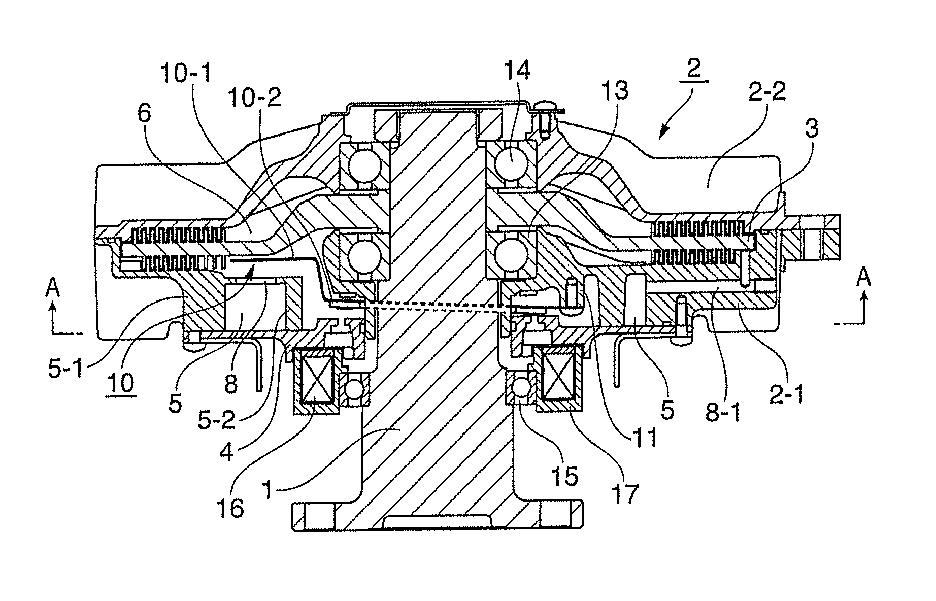
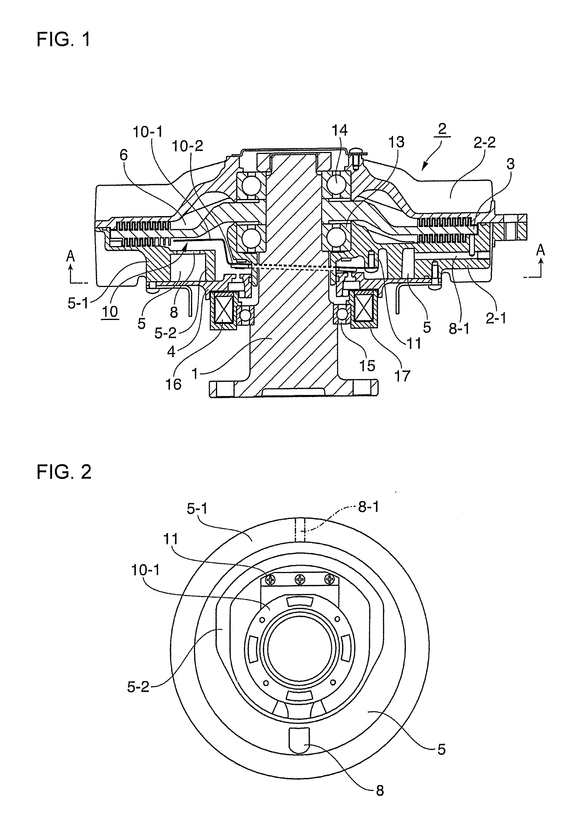
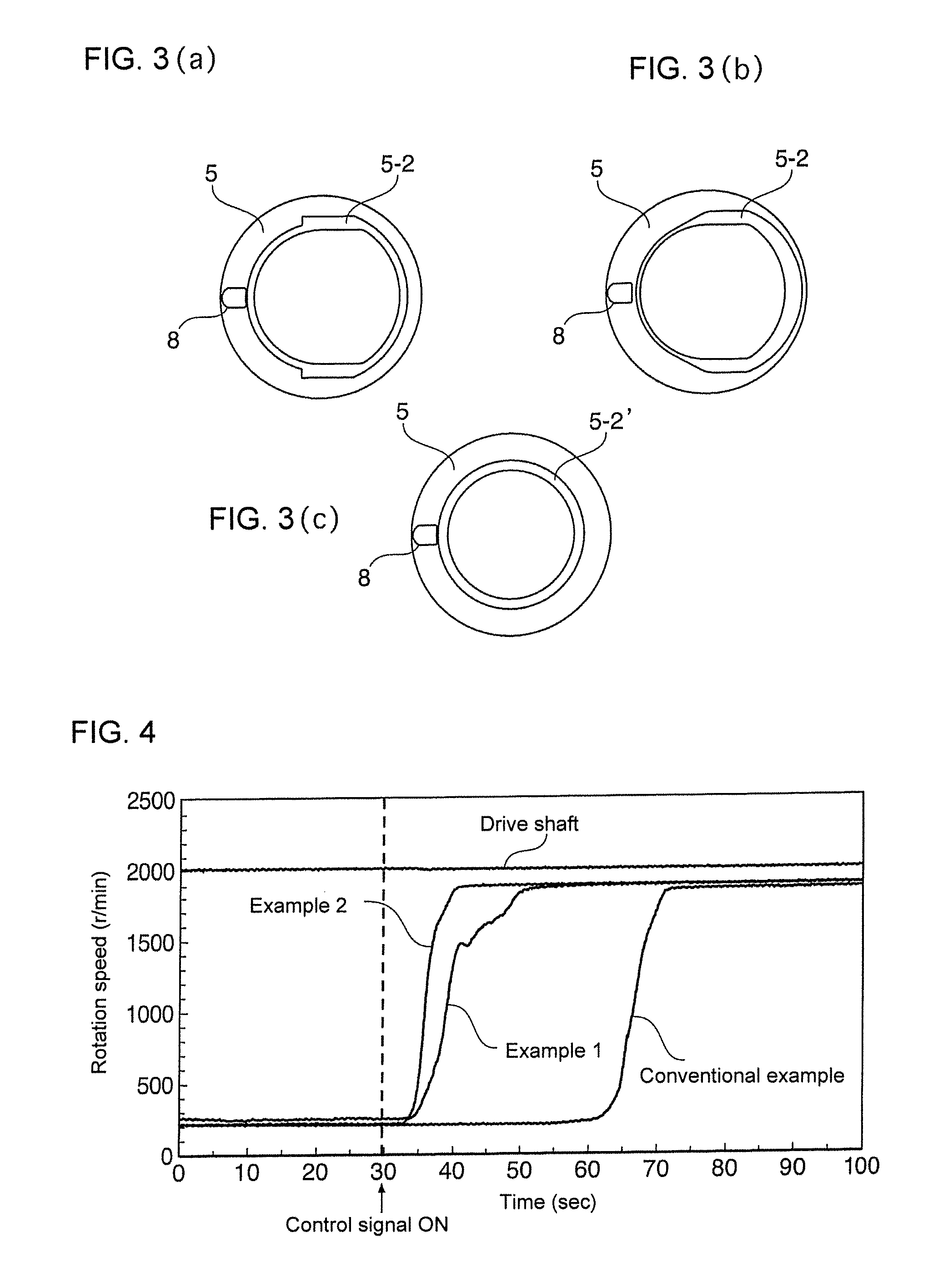
[0018]In a highly reactive fluid fan clutch device of external control type depicted in FIG. 1 and FIG. 2, a sealed housing 2 composed of a case 2-1 and a cover 2-2 is supported via bearings and 14 on a rotary shaft (drive shaft) 1 that rotates by driving of a drive unit (engine), and a drive disk 3 fixed to the rotary shaft 1 is incorporated in a torque transmission chamber 6 within the sealed housing 2. The case 2-1 is provided with an annular oil reserving chamber (oil storage chamber) 5 that has an outer wall 5-1 and an inner wall 5-2 with a hollow therebetween and is covered with a plate 4. The oil reserving chamber 5 is configured so that the inner wall 5-2 is eccentric to the outer wall 5-1. An outer wall 5-1 side of the oil reserving chamber 5 is provided with an oil circulating flow passage hole (oil supply bore) 8 communicating with the torque transmission chamber 6, and an oil recovery port 8-1. An oil supply valve member 10 for opening and closing the oil circulating flo...


PUM


Abstract

Provided is a highly reactive fluid fan clutch device excellent in reaction speed of fan rotation to a control signal even with a weak centrifugal force during low fan rotation. The device of an external control type includes: an annular oil reserving chamber provided in a case that is supported by a rotary shaft having a drive disk fixed thereto; and a valve member for opening and closing an oil circulating flow passage hole of the annular oil reserving chamber by an electromagnet, wherein an effective oil contact area at a torque transmission gap formed between a drive side and a driven side is increased and decreased to control rotation torque transmission from the drive side to the driven side, and an inner wall eccentric to an outer wall of the annular oil reserving chamber is provided in the annular oil reserving chamber.

Description

CROSS REFERENCE TO RELATED APPLICATIONS[0001]The present application claims priority to Japanese Patent Application No. 2014-103779 filed on May 19, 2014, the entire contents of which are incorporated by reference herein.BACKGROUND[0002]1. Field of the Invention[0003]The present invention relates to a fluid fan clutch device of a type in which fan rotation for engine cooling generally in an automobile or the like is controlled according to a change in external ambient temperature or rotation and, in more detail, relates to a highly reactive fluid fan clutch device for improving quickness of reaction of fan rotation to a control signal.[0004]2. Description of the Related Art[0005]Conventionally, as a fan clutch device for controlling fan rotation for engine cooling in an automobile or the like to supply an amount of cooling blast to the engine, there are a temperature-sensitive type, an external control type, and the like. The temperature-sensitive type includes an example of a fan c...

Claims


Application Information

Patent Timeline
Patent Type & Authority Applications(United States)
IPC IPC(8): F16D35/02
CPCF16D35/024
Inventor KUBOTA, SATOSHITAKAHASHI, YOHEI
Owner USUI KOKUSAI SANGYO KAISHA LTD
Why Eureka
Try Eureka