System and Method of Measuring Defects in Ferromagnetic Materials

a technology of ferromagnetic materials and defects, applied in the direction of material magnetic variables, material analysis through optical means, instruments, etc., can solve the problems of sand produced in an oil or gas well abrade the inside, material corrosion and/or erosion, and high cost and time-consuming

Active Publication Date: 2015-11-19
CHARLES STARK DRAPER LABORATORY
View PDF2 Cites 26 Cited by
  • Summary
  • Abstract
  • Description
  • Claims
  • Application Information

AI Technical Summary

Problems solved by technology

In many cases, these materials are subject to corrosion and / or erosion.
For example, sand produced in an oil or gas well can abrade the inside of a pipeline carrying oil or gas from the well.
If allowed to occur beyond a critical point, corrosion or erosion may compromise structural integrity of an item, possibly resulting in a catastrophic failure, such as an oil spill, building collapse or ship sinking.
These steps are costly, time-consuming and often compromise the thermal insulation and / or the surface treatments.
These systems cannot detect defects elsewhere, such as inside the pipe wall or on an outside surface of a pipe, nor can they infer the condition of a pipe due to erosion before the sensor was in place.
Some items, such as pipes, remain unused, and therefore unpressurized, for periods of time during which defects may develop.
Other structures, such as ship hulls or structural elements, do not lend themselves to known pressurization cycling.
However, without pressurization, the Goroshevskiy apparatus and methods cannot detect these defects.
Furthermore, Goroshevskiy can determine a defect's location only along the length of a pipe; Goroshevskiy cannot determine the defect's location circumferentially around the pipe.

Method used


Image

  • System and Method of Measuring Defects in Ferromagnetic Materials
  • System and Method of Measuring Defects in Ferromagnetic Materials
  • System and Method of Measuring Defects in Ferromagnetic Materials

Examples


Embodiment Construction

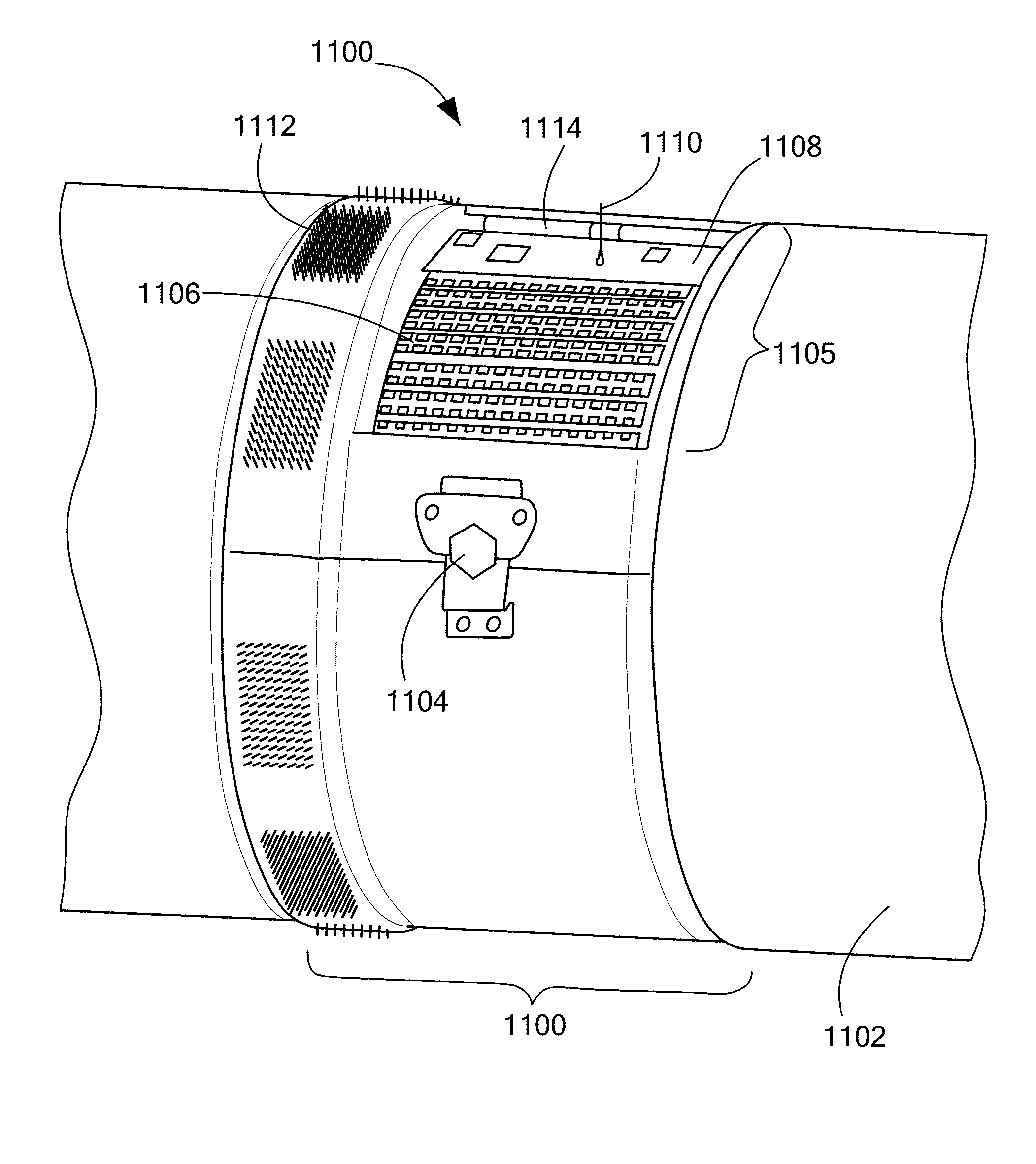
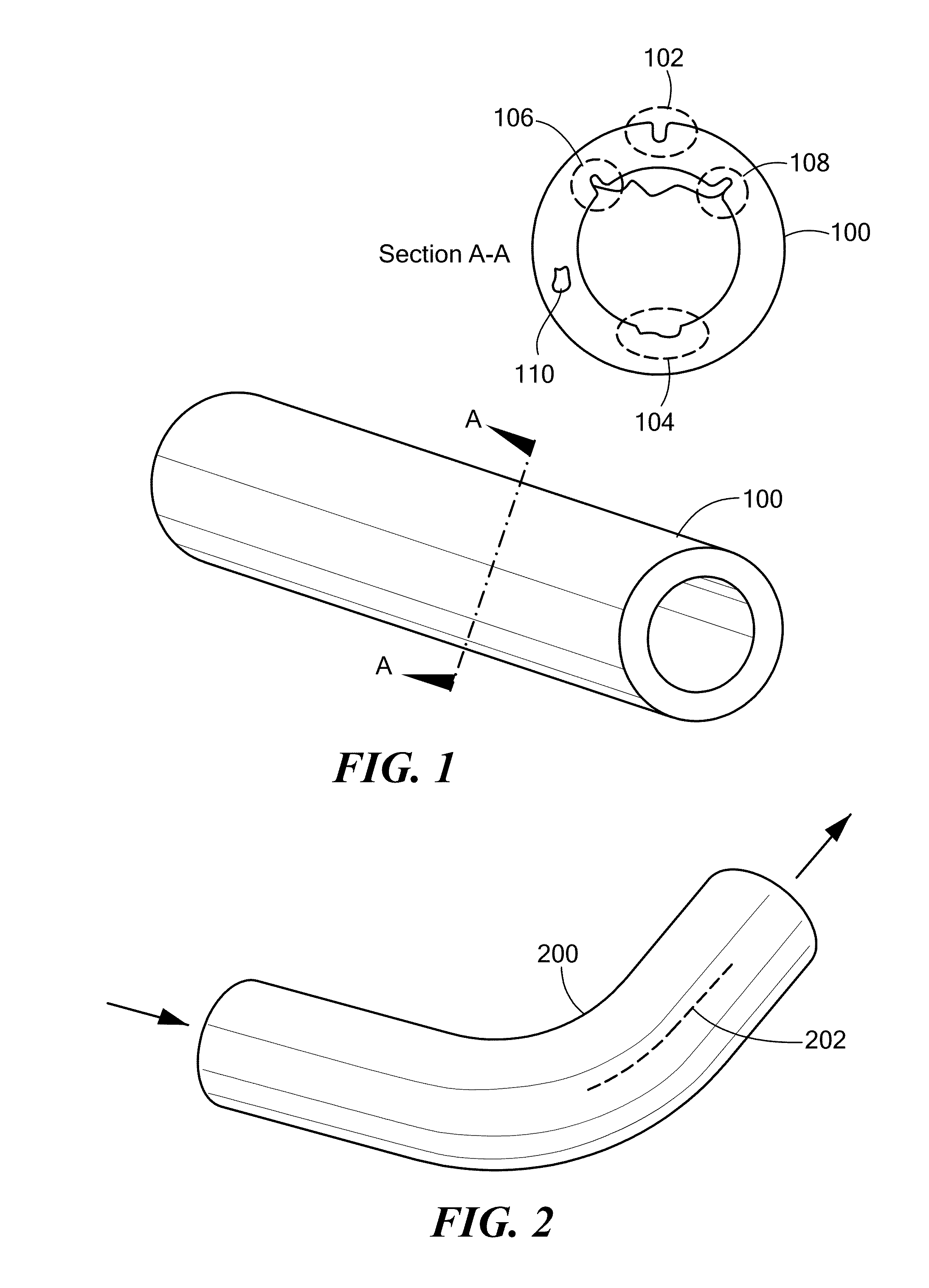
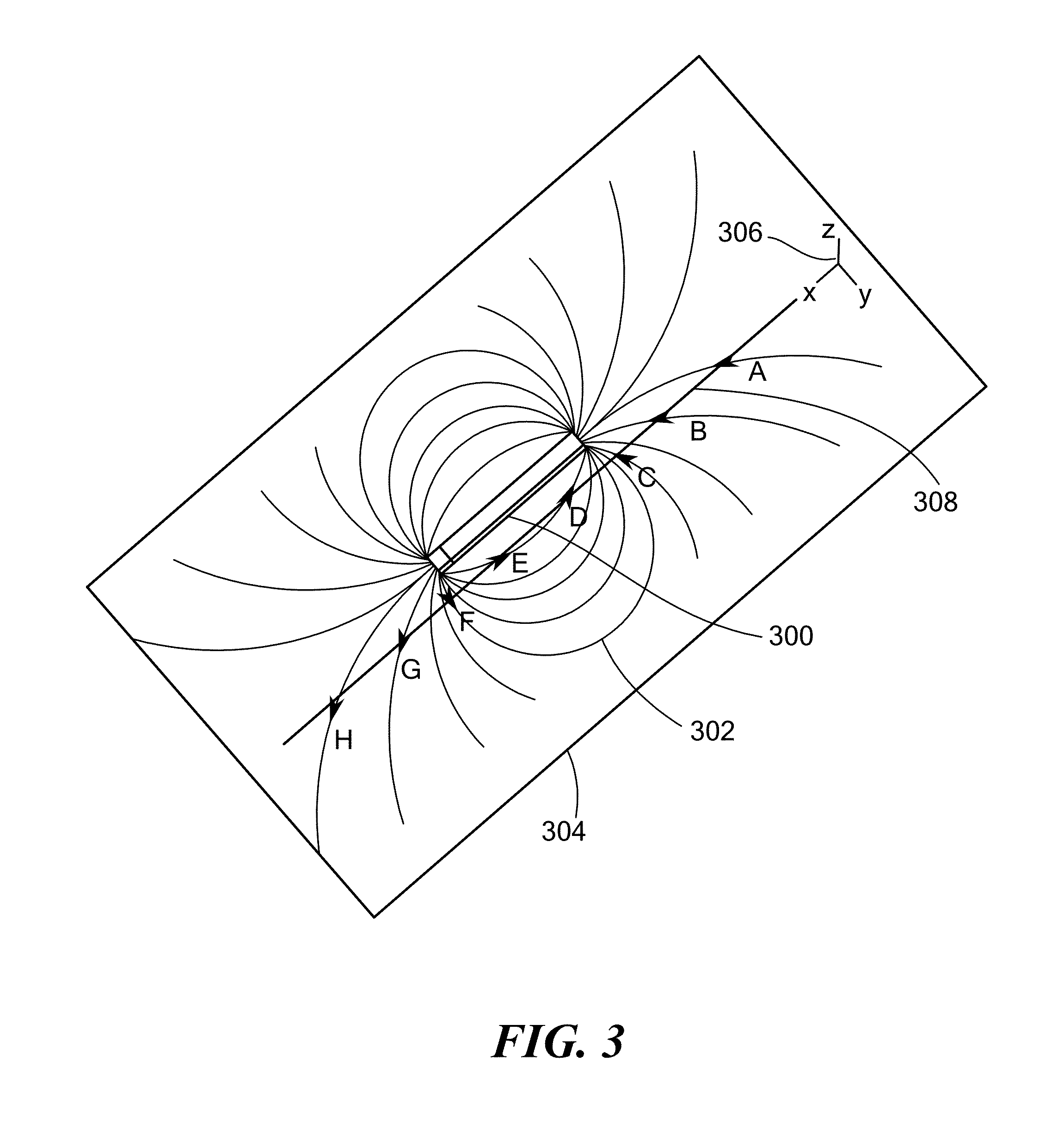
[0007]An embodiment of the present invention provides a system for detecting defects in a ferromagnetic material. The system includes a plurality of magnetometers. The plurality of magnetometers is disposed about a surface of the ferromagnetic material. The plurality of magnetometers senses a magnetic field generated by the ferromagnetic material. The plurality of magnetometers generates magnetic field data, based on the sensed magnetic field. Each magnetometer of the plurality of magnetometers is fixed in position, relative to the ferromagnetic material. The system also includes a magnetic field mapper. The magnetic field mapper generates data points of a two-dimensional map from the magnetic field data. Each data point corresponds to a respective location on the surface of the ferromagnetic material. Each data point represents strength of the sensed magnetic field proximate the location. “Proximate” in this context means close enough so the location of a defect can be determined i...


PUM

PropertyMeasurementUnit
diameteraaaaaaaaaa
diameteraaaaaaaaaa
diameteraaaaaaaaaa

Abstract

Defects in ferromagnetic materials are detected and characterized by analyzing the items' magnetic fields to find portions of the magnetic fields that differ in characteristic ways from residual magnetic fields generated by non-defective portions of the items. The portions of the magnetic fields that differ in the characteristic ways correspond to locations of the defects. The residual magnetic fields correspond to portions of the items distant from the defects. The defect characterization may include volume of material lost due to each defect and / or width and / or depth of each defect.

Description

CROSS-REFERENCE TO RELATED APPLICATIONS[0001]This application claims the benefit of U.S. Provisional Patent Application No. 61 / 994,961, filed May 18, 2014, titled “System and Method of Measuring Defects in Ferromagnetic Materials,” the entire contents of which are hereby incorporated by reference herein, for all purposes.TECHNICAL FIELD[0002]The present invention relates to defect detection in ferromagnetic materials and, more particularly, to defect detection in ferromagnetic materials using a magnetometer.BACKGROUND ART[0003]Ferromagnetic materials, such as iron, nickel, steel and other materials, are used to make many items, such as pipes, beams and ocean vessel hulls. As used herein, “ferromagnetic material” includes both ferromagnetic and ferrimagnetic material. In many cases, these materials are subject to corrosion and / or erosion. As used herein, corrosion means loss of material as a result of chemical reaction, most commonly oxidation. As used herein, erosion means loss of m...

Claims


Application Information

Patent Timeline
Patent Type & Authority Applications(United States)
IPC IPC(8): G01N27/82
CPCG01N27/82G01N17/00G01N2021/8861G01N2021/8864
Inventor DAVIS, ALMIR D.TRINKLE, WILLIAM J.GUSTAFSON, DONALDBABCOCK, IV, PHILIP S.BERTHOLD, RICHARD T.
Owner CHARLES STARK DRAPER LABORATORY
Why Eureka
Try Eureka