Methods, systems and apparatus for detecting material defects in combustors of combustion turbine engines

a technology of combustion turbine engines and material defects, applied in the direction of material magnetic variables, lighting and heating apparatus, instruments, etc., can solve the problems of chain reaction that destroys downstream systems and components, component failure remains a significant concern in combustion turbine engines, and may be nearing the limit of its useful li

Inactive Publication Date: 2012-07-05
GENERAL ELECTRIC CO
View PDF4 Cites 15 Cited by
  • Summary
  • Abstract
  • Description
  • Claims
  • Application Information

AI Technical Summary

Problems solved by technology

Whether due to extreme temperature, mechanical loading or combination of both, component failure remains a significant concern in combustion turbine engines.
A majority of failures can be traced to material fatigue, which typically is forewarned by the onset of crack propagation.
More specifically, the formation of cracks caused by material fatigue remains a primary indicator that a component has reached the limit of its useful life and may be nearing failure.
Such a failure event may cause a chain reaction that destroys downstream systems and components, which require expensive repairs and lengthy forced outages.
However, as one of ordinary skill in the art will appreciate, these types of coatings wear or fragment during usage, a process that is typically referred to as “coating spallation” or “spallation”.
Spallation may result in the formation and growth of uncoated or exposed areas at discrete areas or patches on the surface of the affected component.
These unprotected areas experience higher temperatures and, thus, are subject to more rapid deterioration, including the premature formation of fatigue cracks and other defects.
However, conventional methods generally require regular visual inspection of parts.
While useful, visual inspection is both time-consuming and requires the engine be shutdown for a prolonged period.

Method used


Image

  • Methods, systems and apparatus for detecting material defects in combustors of combustion turbine engines
  • Methods, systems and apparatus for detecting material defects in combustors of combustion turbine engines
  • Methods, systems and apparatus for detecting material defects in combustors of combustion turbine engines

Examples


Embodiment Construction

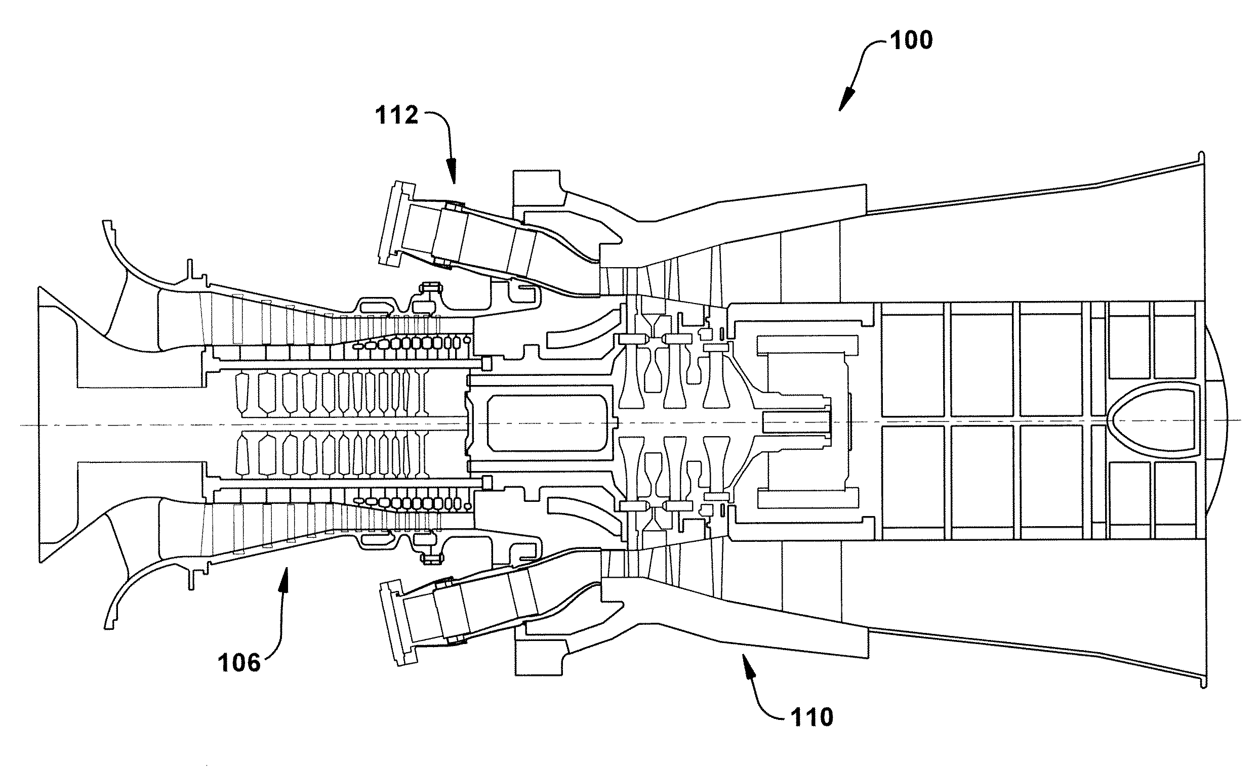
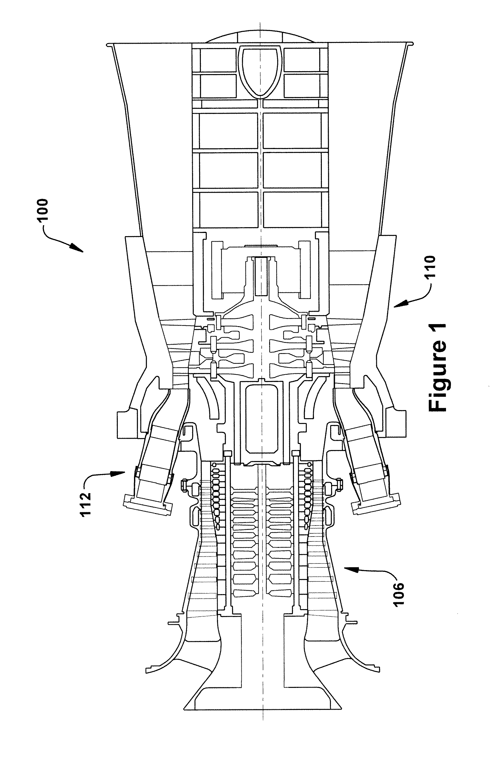
[0023]Referring now to the figures, FIG. 1 illustrates a schematic representation of a gas turbine engine 100 in which embodiments of the present invention may be employed. In general, gas turbine engines operate by extracting energy from a pressurized flow of hot gas that is produced by the combustion of a fuel in a stream of compressed air. As illustrated in FIG. 1, gas turbine engine 100 may be configured with an axial compressor 106 that is mechanically coupled by a common shaft or rotor to a downstream turbine section or turbine 110, and a combustion system 112, which, as shown, is a can combustor that is positioned between the compressor 106 and the turbine 110.

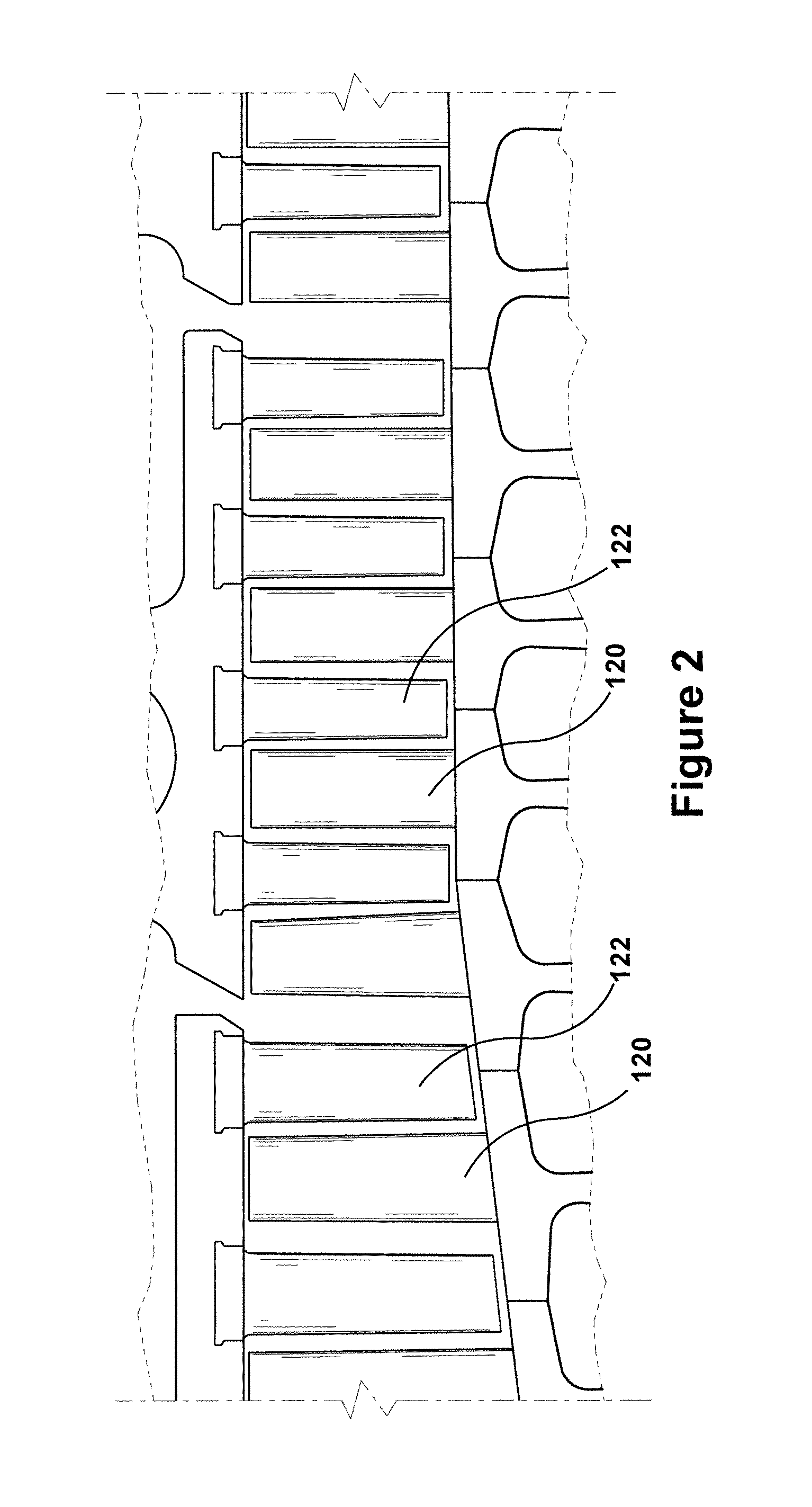
[0024]FIG. 2 illustrates a view of an axial compressor 106 that may be used in gas turbine engine 100. As shown, the compressor 106 may include a plurality of stages. Each stage may include a row of compressor rotor blades 120 followed by a row of compressor stator blades 122. Thus, a first stage may include a row of co...


PUM

PropertyMeasurementUnit
thicknessaaaaaaaaaa
distanceaaaaaaaaaa
threshold temperatureaaaaaaaaaa

Abstract

A system for detecting defects in a combustion duct of a combustion system of a combustion turbine engine while the combustion turbine engine operates, wherein the combustion duct comprises a hot side, which is exposed to combustion gases and, opposing the hot side, a cold side. The system may include: an indicator coating disposed on the cold side of the combustion duct; and a proximity sensor positioned in proximity to the combustion duct and configured to detect a distance between the position of the proximity sensor and the cold side of the combustion duct.

Description

BACKGROUND OF THE INVENTION[0001]This present application relates generally to methods, systems, and apparatus for detecting defects, including surface defects, which may occur in industrial manufacturing processes, engines, or similar systems. More specifically, but not by way of limitation, the present application relates to methods, systems, and apparatus pertaining to the detection of defects that form on the components, such as those found within the combustor, exposed to the hot-gases of combustion turbine engines.[0002]In operation, generally, a combustion turbine engine may combust a fuel with compressed air supplied by a compressor. As used herein and unless specifically stated otherwise, a combustion turbine engine is meant to include all types of turbine or rotary combustion engines, including gas turbine engines, aircraft engines, etc. The resulting flow of hot gases, which typically is referred to as the working fluid, is expanded through the turbine section of the engi...

Claims


Application Information

Patent Timeline
Patent Type & Authority Applications(United States)
IPC IPC(8): G01N27/90G01R27/26G01R27/04
CPCF23M5/02F23M11/00F23N5/242F23R3/002Y02T50/677F23R2900/00019G01B21/16Y02T50/67F23R2900/00005Y02T50/60
Inventor KRISHNA, PRADEEP AADI GOPALAGHOSH, DULLALDUGAR, SAURAVBERKEBILE, MATTHEW PAULKRULL, ANTHONY WAYNE
Owner GENERAL ELECTRIC CO
Why Eureka
Try Eureka