Infrared coherent thermal wave imaging system and detection method based on system

A technology of thermal wave imaging and detection method, which is applied in the field of infrared coherent thermal wave imaging system, can solve the problems of low signal-to-noise ratio and insensitivity of test piece detection, and achieve the effect of improving the effect of material defects and high sensitivity

Active Publication Date: 2017-02-15
HARBIN INST OF TECH
View PDF6 Cites 14 Cited by
  • Summary
  • Abstract
  • Description
  • Claims
  • Application Information

AI Technical Summary

Problems solved by technology

[0004] The purpose of the present invention is to propose an infrared coherent thermal wave imaging system and a detection method based on the system, so as to solve the problems existing in the commonly used infrared thermal imaging nondestruc

Method used


Image

  • Infrared coherent thermal wave imaging system and detection method based on system

Examples


specific Embodiment approach 1

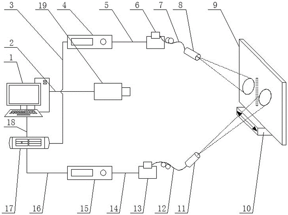
[0026] Specific implementation manner one: such as figure 1 As shown, an infrared coherent thermal wave imaging system is composed of a computer 1, an Ethernet cable 2, a first BNC data line 3, a first laser power supply 4, a first laser power supply line 5, a first laser 6, and a first optical fiber 7. The first collimator 8, the mobile station 10, the second collimator 11, the second optical fiber 12, the second laser 13, the second laser power line 14, the second laser power supply 15, the second BNC data line 16, Function generator 17, USB data cable 18 and infrared thermal imager 19;

[0027] The computer 1 is provided with two signal output terminals. One of the signal output terminals of the computer 1 is connected to the signal input terminal of the infrared camera 19 through the Ethernet cable 2, and the other signal output terminal of the computer 1 is through USB The data line 18 is connected to the signal input end of the function generator 17. The function generator...

specific Embodiment approach 2

[0029] Specific implementation manner two: such as figure 1 As shown, according to an infrared coherent thermal wave imaging system according to the first embodiment, the first laser 6 and the second laser 13 are both 808nm semiconductor lasers; the first laser power supply 4 and the second laser The power supplies 15 are all 808nm semiconductor laser power supplies.

specific Embodiment approach 3

[0030] Specific implementation manner three: such as figure 1 As shown, a detection method based on an infrared coherent thermal wave imaging system described in Embodiment 1 or 2, the detection method includes the following steps:

[0031] Step 1: Fix the tested sample 9 on the mobile platform 10 (the mobile platform 10 can control the vertical and horizontal movement of the tested sample 9); in this embodiment, the thickness of the tested sample 9 is 4 mm , Take a square block with a size of 10cm×10cm as an example, the tested specimen 9 is made of CFRP material, and the tested specimen 9 is prefabricated with micro-crack defects;

[0032] Step 2: Turn on the computer 1, the first laser power supply 4, the first laser 6, the second laser 13, the second laser power supply 15, the function generator 17, and the infrared thermal imager 19 in the infrared coherent thermal wave imaging system ;

[0033] Step 3: Set the peak power of the first laser and the second laser to 30W respecti...


PUM


Abstract

An infrared coherent thermal wave imaging system and a detection method based on the system belong to the field of infrared imaging nondestructive detection. Two signal output ends of a computer are connected with signal input ends of an infrared thermal imager and a function generator correspondingly; two signal output ends of the function generator are connected with signal input ends of a first laser power supply and a second laser power supply correspondingly; current output ends of the first laser power supply and the second laser power supply are connected with current input ends of a first laser and a second laser correspondingly; laser output ends of the first laser and the second laser are connected with laser input ends of a first collimating mirror and a second collimating mirror correspondingly; and a moving platform is arranged in front of the first collimating mirror and the second collimating mirror. A tiny defect of a detected test piece is detected by a double-beam coherent laser coherent subtraction principle, the disadvantage that the traditional detection method is insensitive on tiny defect detection is overcome, and the signal to noise ratio of detecting a material defect by infrared thermal wave is greatly increased by a coherent excitation loading mode.

Description

Technical field [0001] The invention relates to an infrared coherent thermal wave imaging system and a detection method based on the system, belonging to the field of infrared imaging nondestructive detection. Background technique [0002] With the rapid development of aerospace, microelectronics, nuclear power and other fields, a series of new thin-layer materials with higher mechanical properties or electrical properties continue to emerge. These materials are widely used in various fields of the national economy. Due to the gradual improvement of product performance requirements, the quality assurance of thin-layer materials in the processing technology has attracted more and more attention from consumers. Unreasonable processing processes are likely to cause many different defects inside the product, such as micro-cracks caused by the residual stress of the product, pores and bulges caused by the prepreg resin of composite materials, and desoldering phenomenon during solderin...

Claims


Application Information

Patent Timeline
IPC IPC(8): G01N25/72
CPCG01N25/72
Inventor 刘俊岩王飞宋鹏冀嘉琦王扬
Owner HARBIN INST OF TECH
Why Eureka
Try Eureka