
Transducer sound arrangement for pocket-forming

a technology of transducer and pocket, which is applied in the direction of transformers, inductances, transportation and packaging, etc., can solve the problems of reducing the capacity of the battery attached to the device, affecting the transmission efficiency of wireless sound, and affecting the transmission efficiency of the device, so as to improve the capability and efficiency of the transmitter, and avoid power loss during wireless sound transmission.

Active Publication Date: 2015-11-19
ENERGOUS CORPORATION
View PDF0 Cites 235 Cited by
  • Summary
  • Abstract
  • Description
  • Claims
  • Application Information

AI Technical Summary

Benefits of technology

This patent describes a method to improve the efficiency and capability of wireless sound power transmitters. This is achieved by using different arrangements of transducer elements that can operate at different frequency bands. This allows for better stability and less power loss during wireless sound power transmission. The patent describes various arrangements of transducer elements such as single array, pair array, quad array, and other suitable configurations. The technical effects of this patent are better and more efficient wireless sound power transmission for various devices that operate at different frequency bands.

Problems solved by technology

The frequent use of these devices may require as significant amount of power, which may easily deplete the batteries attached to these devices.
Therefore, a user is frequently needed to plug in the device to a power source, and recharge such device.
This may be inconvenient and troublesome if the user forgets to plug in or otherwise charge a device, the device may run out of power and be of no use to the user until the user is again able to charge the device.
Solar-powered battery chargers are also known, however, solar cells are expensive, and a large array of solar cells may be required to charge a battery of any significant capacity.
Such power transmission is wasteful, as most of the energy would be transmitted and not received by the intended devices, it could be hazardous to living tissue, it would most likely interfere with most electronic devices in the immediate vicinity, and it may be dissipated as heat.
However, even when the device is located, efficient transmission is not guaranteed due to reflections and interference of objects in the path or vicinity of the receiving device.

Method used


Image

  • Transducer sound arrangement for pocket-forming
  • Transducer sound arrangement for pocket-forming
  • Transducer sound arrangement for pocket-forming

Examples


Embodiment Construction

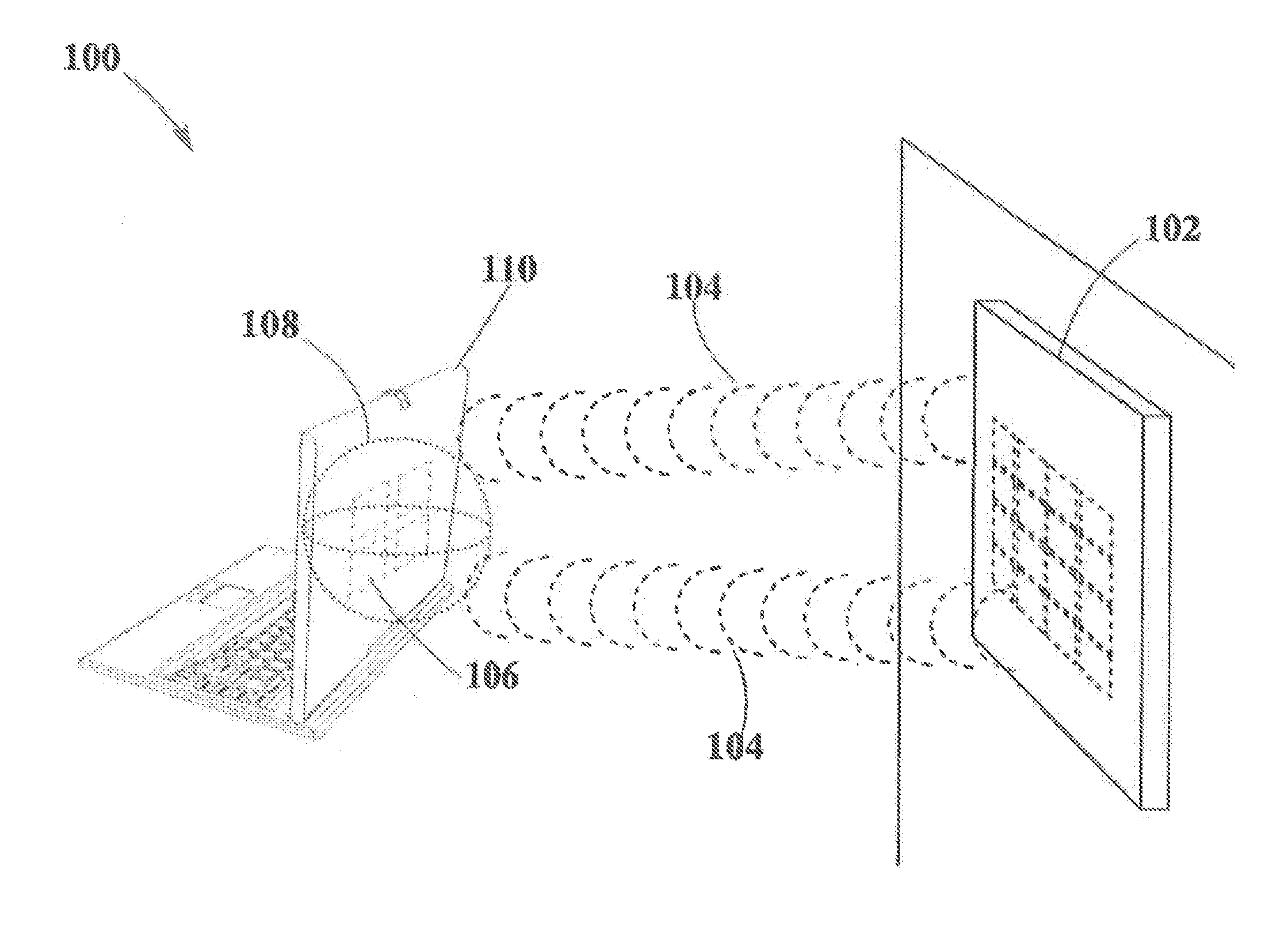
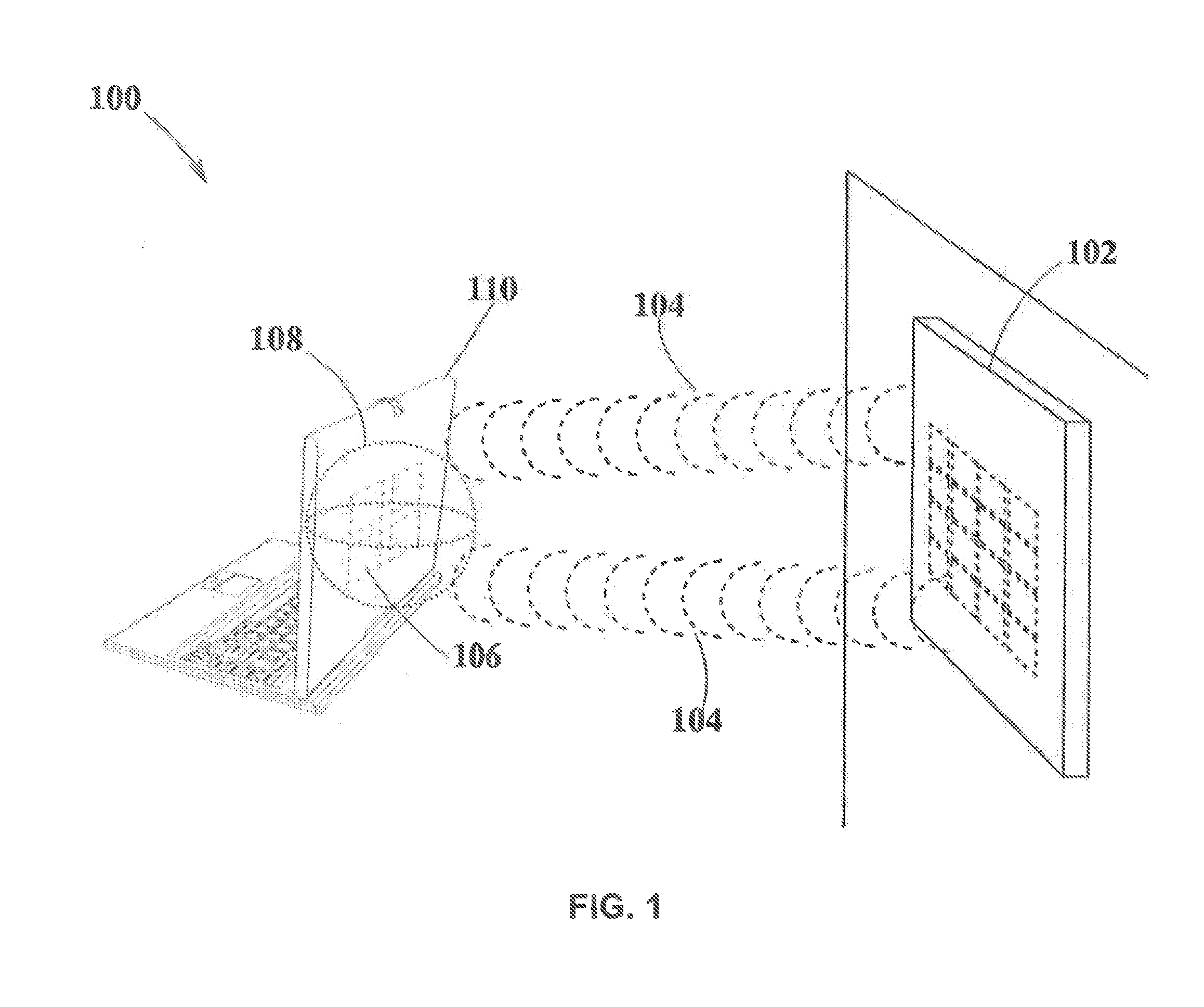
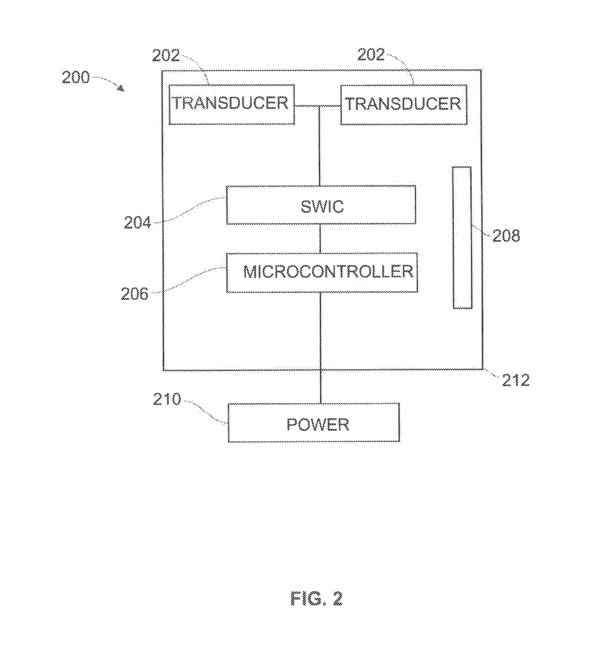
[0037]In example #1 a portable electronic device that may operate at 10 KHz may be powered or charged. In this example, a transmitter as the one described in FIG. 2, may be used to deliver pockets of energy onto one electronic device, as in FIG. 1. This transmitter may have a single array of 8×8 of flat panel transducers where all the transducer elements may operate in the frequency band of 10 KHz. Flat transducers may occupy less volume than other transducers, hence allowing a transmitter to be located at small and thin spaces, such as, walls, mirrors, doors, ceilings and the like. In addition, flat panel transducers may be optimized for operating to long distances into narrow hall of wireless power transmission, such feature may allow operation of portable devices in long areas such as, train stations, bus stations, airports and the like. Furthermore, flat panel transducers of 8×8 may generate smaller pockets of energy than other transducers since its smaller volume, this may redu...


PUM


Abstract

The present disclosure describes a plurality of transducer arrangements that may be suitable for wireless power transmission based on single or multiple pocket-forming. Single or multiple pocket-forming may include one transmitter and at least one or more receivers, being the transmitter the source of energy and the receiver the device that is desired to charge or power. The transducer arrangements may vary in size and geometry, and may operate as a single array, pair array, quad arrays or any other suitable arrangement, which may be designed in accordance with the desired application.

Description

CROSS-REFERENCES TO RELATED APPLICATIONS[0001]The present disclosure is related to U.S. Non-Provisional patent application Ser. No. 13 / 891,399 filed May 10, 2013, entitled “Receivers For Wireless Power Transmission”; Ser. No. 13 / 891,430 filed May 10, 2013, entitled “Methodology For Pocket-forming” and Ser. No. 13 / 891,455 filed May 10, 2013, entitled “Transmitters For Wireless Power Transmission”, the entire contents of which are incorporated herein by these references.FIELD OF INVENTION[0002]The present disclosure relates to wireless sound power transmission, and more particularly to the transducer arrangements for wireless power transmission based on pocket-forming.BACKGROUND OF THE INVENTION[0003]Portable electronic devices such as smart phones, tablets, notebooks and others, have become an everyday need in the way we communicate and interact with others. The frequent use of these devices may require as significant amount of power, which may easily deplete the batteries attached t...

Claims


Application Information

Patent Timeline
Patent Type & Authority Applications(United States)
IPC IPC(8): H02J5/00H02J17/00H02J7/02
CPCH02J5/005H02J17/00H02J7/025H02J50/20H02J7/35H02J50/10H02J50/80H02J50/402H02J50/15
Inventor LEABMAN, MICHAEL A.
Owner ENERGOUS CORPORATION
Learn More