Continuously variable transmission

a transmission belt and variable technology, applied in the direction of gearing elements, driving belts, gearing pulleys, etc., can solve the problems of power transmission loss between the drive pulley and the transmission belt, and achieve the reduction of the thrust force exerted in the first pulley, the reduction of the shift of the belt track, and the reduction of the power transmission loss

Active Publication Date: 2021-07-08
TOYOTA JIDOSHA KK
View PDF0 Cites 0 Cited by
  • Summary
  • Abstract
  • Description
  • Claims
  • Application Information

AI Technical Summary

Benefits of technology

[0015]The continuously variable transmission thus configured can reduce the power transmission loss between each tapered surface and the elements.
[0016]In the continuously variable transmission according to the present disclosure, the thrust force exerted in the first pulley can be reduced compared with when, in the belt track for the minimum gear ratio, each tapered surface of the first pulley has the same coefficient of friction relative to the transmission belt at the portion in contact with the transmission belt as each of the tapered surfaces of the second fixed sheave and the second movable sheave does at the portion in contact with the transmission belt. Since the thrust force exerted in the first pulley at the minimum gear ratio can be thus reduced, sheave deformation in which the first fixed sheave and the first movable sheave holding the transmission belt therebetween warp outward in the axial direction can be mitigated accordingly, so that shift of the belt track can be reduced. As a result, power transmission loss between

Problems solved by technology

Therefore, at the side of the drive pulley where the transmission belt enters the drive pulley, the area of contact between the drive pulley and the transmissi

Method used


Image

  • Continuously variable transmission
  • Continuously variable transmission
  • Continuously variable transmission

Examples


Embodiment Construction

[0028]One embodiment of a continuously variable transmission according to the present disclosure will be described below. The present disclosure is not limited by this embodiment.

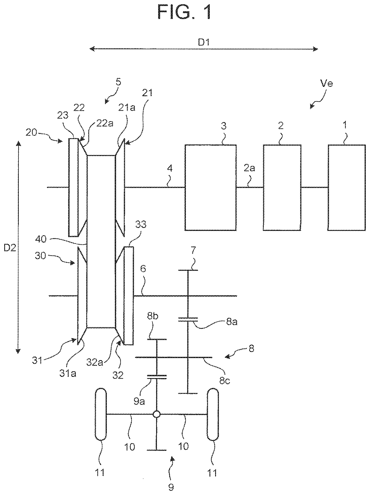
[0029]FIG. 1 is a skeleton diagram schematically showing a power transmission mechanism of a vehicle Ve equipped with a continuously variable transmission 5. As shown in FIG. 1, the vehicle Ve includes an engine 1 as a power source. Power output from the engine 1 is input into the belt-driven continuously variable transmission 5 through a torque converter 2, a forward-backward travel switching mechanism 3, and an input shaft 4, and is transmitted from the continuously variable transmission 5 to a counter gear mechanism 8, a differential mechanism 9, axles 10, and drive wheels 11 through an output shaft 6 and an output gear 7. The input shaft 4 is one example of the “first rotating shaft” of the present disclosure, and the output shaft 6 is one example of the “second rotating shaft” of the present disclosure...


PUM


Abstract

Provided is a continuously variable transmission including: a first pulley including a first fixed sheave fixed to a first rotating shaft and a first movable sheave rotating integrally with the first rotating shaft and is movable along the first rotating shaft; a second pulley including a second fixed sheave fixed to a second rotating shaft and a second movable sheave rotating integrally with the second rotating shaft and is movable along the second rotating shaft; and a transmission belt wrapped around a belt wrapping groove formed on the first pulley and around a belt wrapping groove formed on the second pulley. In a belt track for a minimum gear ratio, surfaces of the first pulley that are in contact with the transmission belt have a lower coefficient of friction relative to the transmission belt than surfaces of the second pulley that are in contact with the transmission belt.

Description

CROSS-REFERENCE TO RELATED APPLICATION[0001]This application claims priority to Japanese Patent Application No. 2020-001625 filed on Jan. 8, 2020, incorporated herein by reference in its entirety.BACKGROUND1. Technical Field[0002]The present disclosure relates to a continuously variable transmission.2. Description of Related Art[0003]The belt-driven continuously variable transmission described in WO 2012 / 144023 includes two rotating shafts disposed parallel to each other, a drive pulley and an idler pulley provided respectively on these rotating shafts, and a transmission belt wrapped around belt wrapping grooves that are V-shaped grooves formed in the drive pulley and the idler pulley. When power from a power source mounted in the vehicle is input into the drive pulley through the rotating shaft, the power is transmitted from the drive pulley to the transmission belt by the force of friction between the drive pulley and the transmission belt. When power is transmitted from the tran...

Claims


Application Information

Patent Timeline
IPC IPC(8): F16H9/18F16G5/16
CPCF16H9/18F16G5/16F16H55/56F16G1/24F16H55/36
Inventor INASE, YUNINOMIYA, KEISUKE
Owner TOYOTA JIDOSHA KK
Why Eureka
Try Eureka