
A direct speed-up type continuously variable transmission chain structure of a wind turbine

A wind turbine and transmission chain technology, applied in the field of transmission chains, can solve the problems of high manufacturing cost, large temperature coefficient of rare earth permanent magnet materials, complex structure, etc., to reduce power transmission loss, expand speed output range, and high transmission efficiency Effect

Inactive Publication Date: 2017-05-24
ZHEJIANG UNIV
View PDF4 Cites 0 Cited by
  • Summary
  • Abstract
  • Description
  • Claims
  • Application Information

AI Technical Summary

Problems solved by technology

Although the direct-drive wind turbine does not need a gearbox to increase speed, which improves the transmission efficiency and reliability and reduces the point of failure, the direct-drive unit has the following disadvantages: the number of pole pairs of the generator is high, the volume is relatively large, and the structure is complicated. The post-manufacturing cost of magnetic materials is high, and with the increase of unit capacity, it will bring difficulties to motor design, manufacturing, and transportation; the temperature coefficient of rare earth permanent magnet materials is large, and the output voltage will change when the load or the ambient temperature changes , which directly affects the normal operation of electric loads

Method used


Image

  • A direct speed-up type continuously variable transmission chain structure of a wind turbine
  • A direct speed-up type continuously variable transmission chain structure of a wind turbine
  • A direct speed-up type continuously variable transmission chain structure of a wind turbine

Examples


Embodiment Construction

[0024] In order to make the purpose, technical solution and advantages of the present invention clearer, the present invention will be described in detail below in conjunction with the accompanying drawings and embodiments. It should be understood that the specific embodiments described here are only used to explain the present invention, not to limit the present invention.

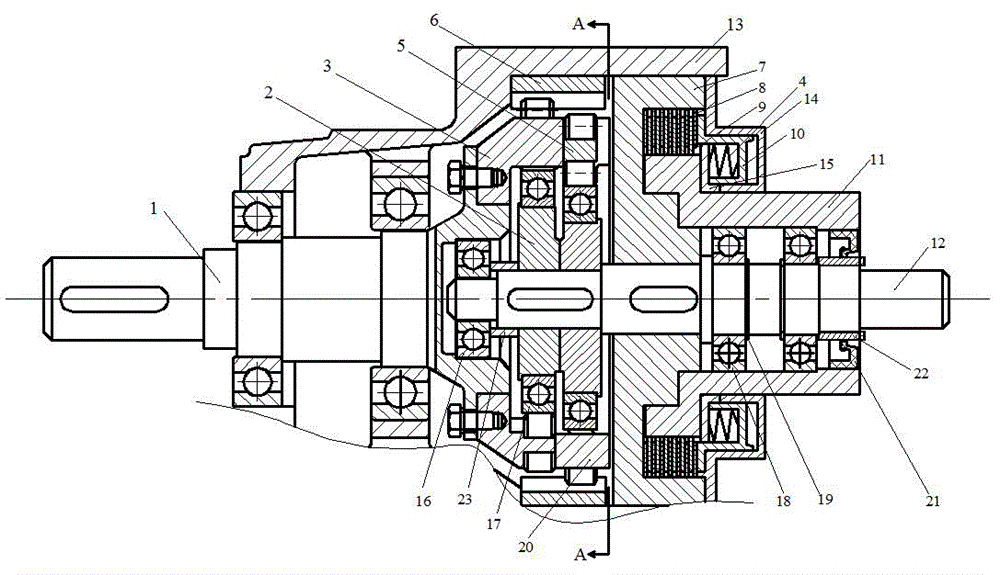
[0025] Such as figure 1 As shown, the present invention includes the wind wheel main shaft 1 and the speed-regulating output shaft 12 installed in the hub 13 through bearings, and also includes a transmission speed-up mechanism and a speed-regulating transmission mechanism. The wind wheel main shaft 1 is installed in the hub 13 through bearings, and the wind wheel The wheel main shaft 1 is fixedly connected with the speed-regulating output shaft 12 through the transmission speed-up mechanism, the speed-regulating output shaft 12 is connected with the speed-regulating transmission mechanism, and the speed-...


PUM


Abstract

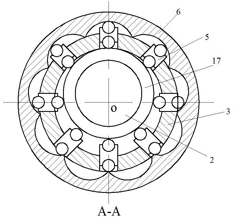
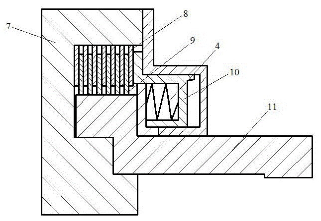
The invention discloses a direct speedup type continuous variable transmission chain structure of a wind power generation set. The direct speedup type continuous variable transmission chain structure comprises a wind wheel main shaft, a speed regulation output shaft, a transmission speedup mechanism and a speed regulation transmission mechanism, wherein the wind wheel main shaft and the speed regulation output shaft are arranged in a wheel hub; the wind wheel main shaft is fixedly connected with the speed regulation output shaft through the transmission speedup mechanism; the speed regulation output shaft is connected with the speed regulation transmission mechanism; the speed regulation output shaft is connected with a subsequent power generator device after speed regulation through the speed regulation transmission mechanism; the transmission speedup mechanism comprises an eccentric sleeve, a second bearing, a radial sliding column, a rotating wheel and an inner gear ring; the speed regulation transmission mechanism comprises a driving shaft, a driving friction piece, a driven friction piece, a hydraulic cylinder control type annular piston and a driven shaft. According to the direct speedup type continuous variable transmission chain structure of the wind power generation set, the direct speedup can be implemented, the structure is compact, the size is small, the weight is light, and the rotating speed can be continuously regulated.

Description

technical field [0001] The invention relates to a transmission chain in the technical field of wind power generation, in particular to a direct speed-up and continuous speed-variation transmission chain structure of a wind turbine. Background technique [0002] With the rapid development of the wind power industry at home and abroad, the technology of wind turbines continues to develop. Among the functional components of wind turbines, the transmission chain of wind turbines is a key component in the process of energy conversion and transmission, which directly affects the performance and efficiency of the entire system. and power quality. Therefore, it is of great significance to develop a safe, reliable, economical, simple and efficient transmission chain. [0003] There are mainly two types of transmission chains for wind turbines: gearbox speed-increasing wind turbines and direct-drive wind turbines; in the current large-scale wind turbines, these two types of wind turb...

Claims


Application Information

Patent Timeline
Patent Type & Authority Patents(China)
IPC IPC(8): F03D15/00F03D9/25
CPCF05B2260/40F05B2260/402F05B2260/4031Y02E10/72
Inventor 殷秀兴罗冲林勇刚李伟刘宏伟
Owner ZHEJIANG UNIV
Learn More