Rotary electric machine

a rotary electric machine and electric motor technology, applied in the field of electrotechnology, can solve problems such as general undesirableness, and achieve the effect of reducing the generation of interfering electromagnetic emission signals

Active Publication Date: 2015-11-19
BROSE FAHRZEUGTEILE GMBH & CO KG HALLSTADT (DE)
View PDF8 Cites 7 Cited by
  • Summary
  • Abstract
  • Description
  • Claims
  • Application Information

AI Technical Summary

Benefits of technology

[0008]In it therefor an object of the present invention to minimize the generation of interfering electromagnetic emission signals by effective connection of

Problems solved by technology

This electromagnetic effect can act on the control circuit, for example, but also on other unit

Method used


Image

  • Rotary electric machine
  • Rotary electric machine
  • Rotary electric machine

Examples


Embodiment Construction

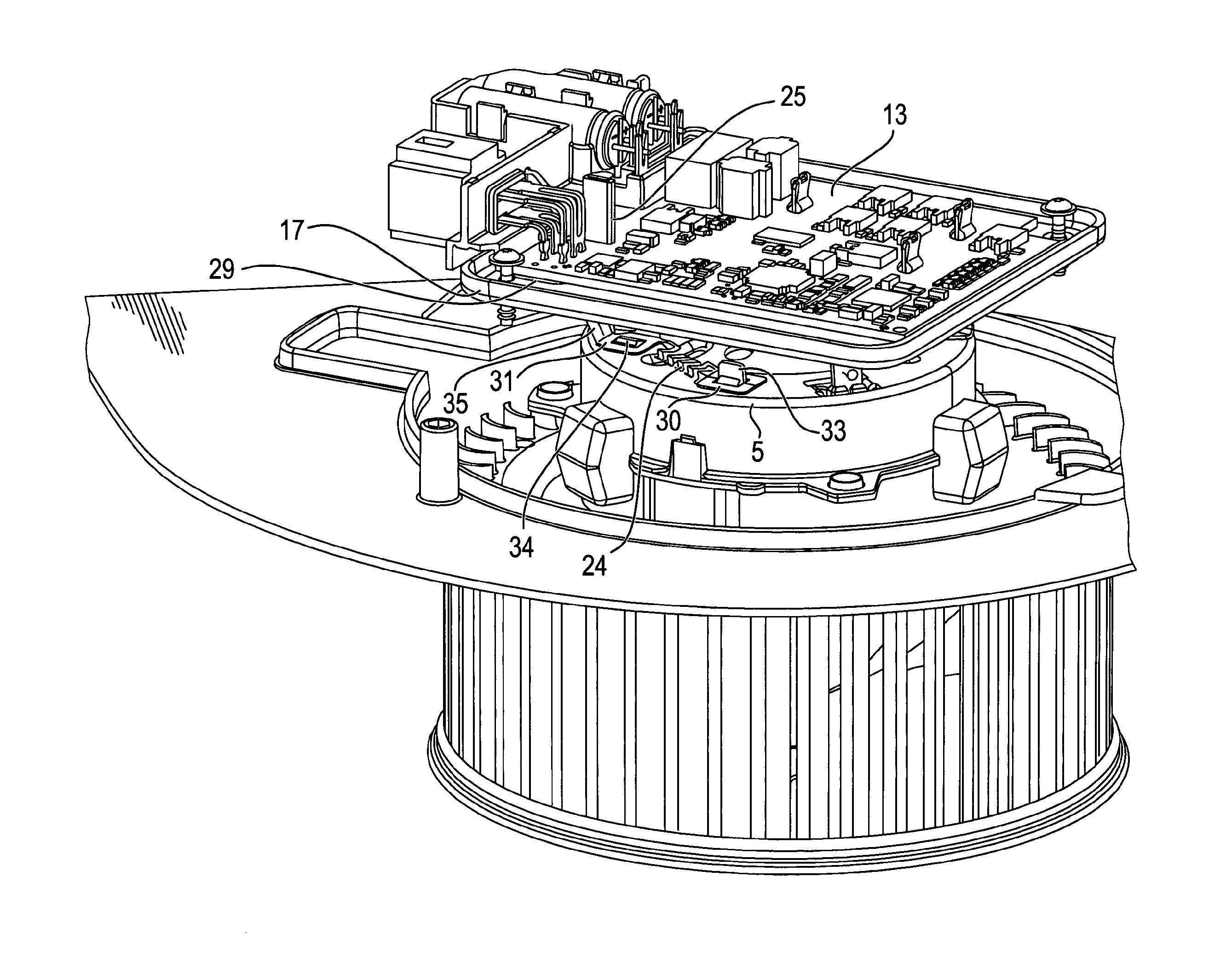
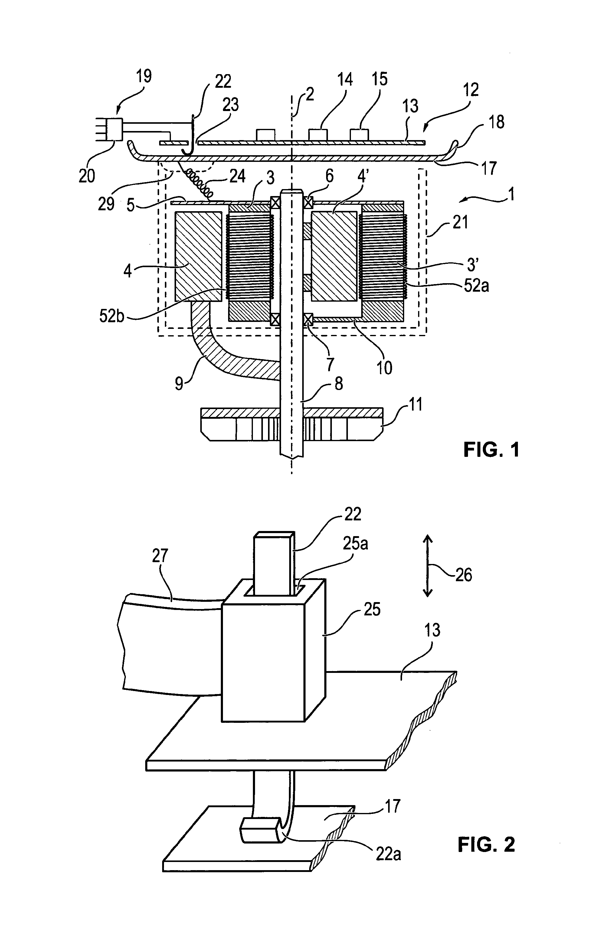
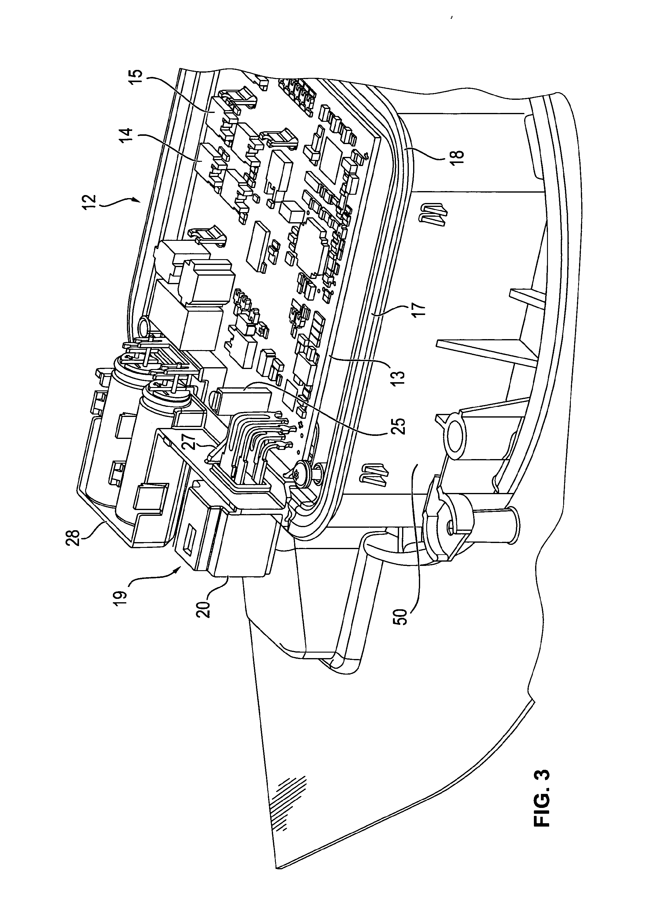
[0048]FIG. 1 shows an electric machine in an overview in a longitudinal section in the example of a brushless electric motor 1.

[0049]Different configurations are illustrated on the left and right side of middle line 2. A brushless electric motor with an inner stator 3 and an outer rotor 4 is illustrated in a half-section on the left side. The inner stator is connected to a face-side end shield 5. A shaft 8 is mounted rotatably opposite to the end shield via a first bearing 6 and a second bearing 7 each of which can be formed identically in the left and right half-section.

[0050]In the machine shown in the left half-section, outer rotor 4 is connected via webs or a bell-shaped structure 9 to shaft 8 and supported by it. Moreover, outer rotor 4 can be mounted on end shield 5 via a ball bearing (not shown).

[0051]An electric motor with an inner rotor is shown on the right side of the section in FIG. 1, so that rotor 4′ is located radially inside stator 3′. Stator 3′ is fixedly connected ...


PUM


Abstract

A rotary electric machine having a stator and a rotor, in addition to an electric control device and a connection device which comprises at least one coupling element for electrically connecting the control device to one or several electrical lines and a mass element provided to connect to an electric mass potential. In order to improve the machine with respect to electromagnetic interference, the stator is connected to the mass element by a contact bridge which has a first securing section and a second securing section in addition to a bridge element arranged between the securing sections and includes a single-piece spring steel sheet which is at least partially sinuous.

Description

[0001]This nonprovisional application is a continuation of International Application No. PCT / EP2014 / 000189, which was filed on Jan. 24, 2014, and which claims priority to German Patent Application No. 10 2013 001 314.3, which was filed in Germany on Jan. 26, 2013, and which are both herein incorporated by reference.BACKGROUND OF THE INVENTION[0002]1. Field of the Invention[0003]The invention relates to the field of electrotechnology and can be used in rotary electric machines, particularly electric motors and generators.[0004]2. Description of the Background Art[0005]In more recent times rotary electric machines, particularly electric motors, but generators as well, are often designed as so-called brushless machines, whereby accordingly direct electric contacting of a rotor by brushes is not necessary. The rotor can be equipped with permanent magnets, which are driven in a rotating magnetic field of the stator. The stator has stator windings for this purpose, which are controlled ac...

Claims


Application Information

Patent Timeline
IPC IPC(8): H02K5/22H01R13/02H02K11/00
CPCH02K5/225H01R13/02H02K11/0073H02K11/022H02K11/01H02K11/40H02K11/33H02K11/0141
Inventor BERKOUK, MAURADLABAT, SEBASTIENFOURNIER, ERIC
Owner BROSE FAHRZEUGTEILE GMBH & CO KG HALLSTADT (DE)
Why Eureka
Try Eureka