
Method and apparatus for calibrating distortion of signals

a technology of calibrating apparatus and signal, which is applied in the direction of electrical apparatus, transmitter monitoring, amplifiers, etc., can solve the problems of i/q mismatch in the frequency mixer, the modulation accuracy of a communication signal may deteriorate, and the communication standard may not be satisfied, so as to achieve effective search

Active Publication Date: 2015-11-19
SAMSUNG ELECTRONICS CO LTD
View PDF2 Cites 18 Cited by
  • Summary
  • Abstract
  • Description
  • Claims
  • Application Information

AI Technical Summary

Benefits of technology

The present patent aims to solve the problem of effectively searching for a control code to calibrate the distortion of a signal. The invention offers a method and apparatus to facilitate this process.

Problems solved by technology

However, a Local Oscillator (LO) leakage signal (or carrier leakage) may act as an interference signal in the frequency mixer, and thus, the required wireless communication standard may not be satisfied or the modulation accuracy of a communication signal may deteriorate.
In addition, I / Q mismatch may occur in the frequency mixer.
The I / Q mismatch refers to a mismatch of a size (or gain) and a phase between transfer characteristics of the I-path and the Q-path of the front end including the frequency mixer of the transceiver, and the I / Q mismatch may generate an image signal of a modulation signal and may deteriorate the quality of a transmission signal.
However, the method still requires a large number of searches and there is a large probability of failing an optimal code Iopt and Qopt when I / Q code searching is insufficiently repeated.

Method used


Image

  • Method and apparatus for calibrating distortion of signals
  • Method and apparatus for calibrating distortion of signals
  • Method and apparatus for calibrating distortion of signals

Examples


Embodiment Construction

[0032]Hereinafter, embodiments of the present disclosure are described in detail with reference to the accompanying drawings. Further, in the following description of the present disclosure, a detailed description of known functions and configurations incorporated herein are omitted when it may obfuscate the subject matter of the present disclosure. The terms described below are terms defined in consideration of the functions in the present disclosure, and may be different according to users, intentions of the users, or customs. Accordingly, the definitions of the terms should be made on the basis of the overall context of the present disclosure.

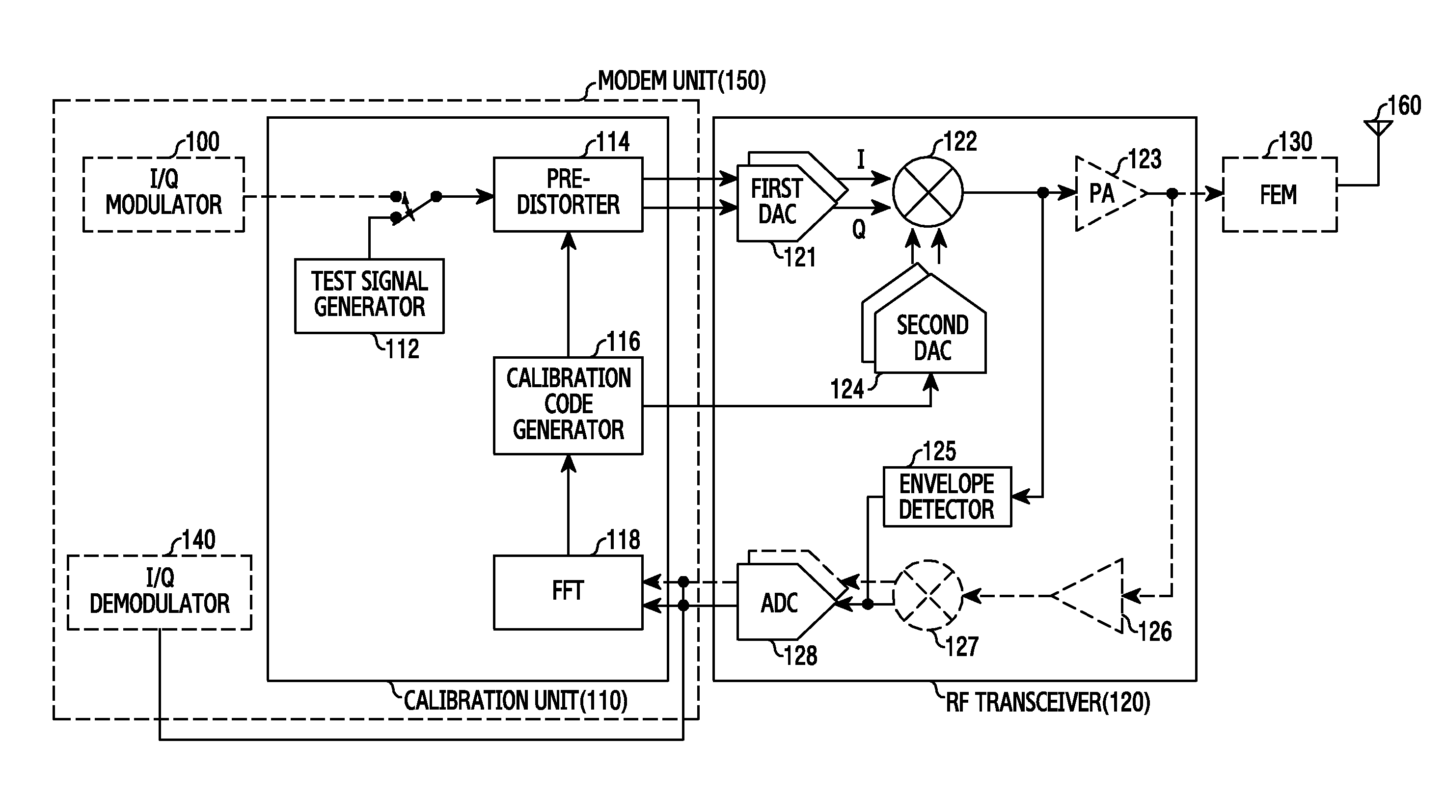
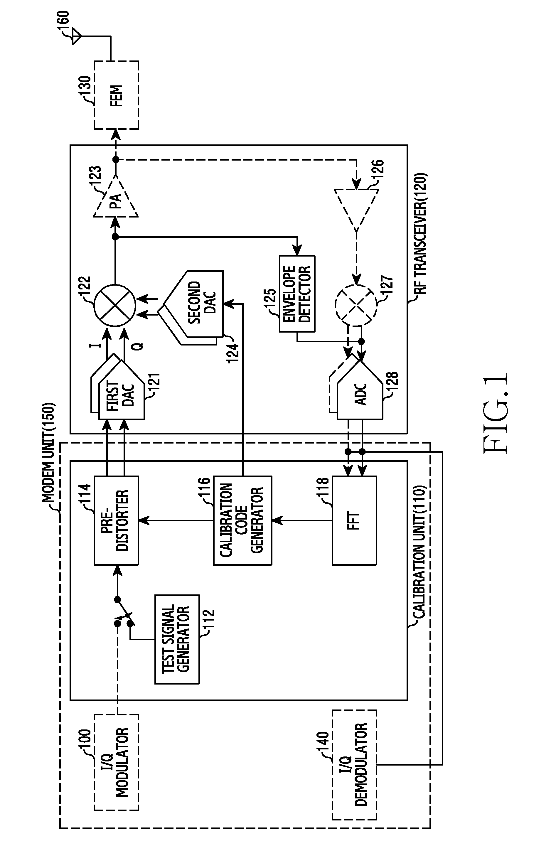
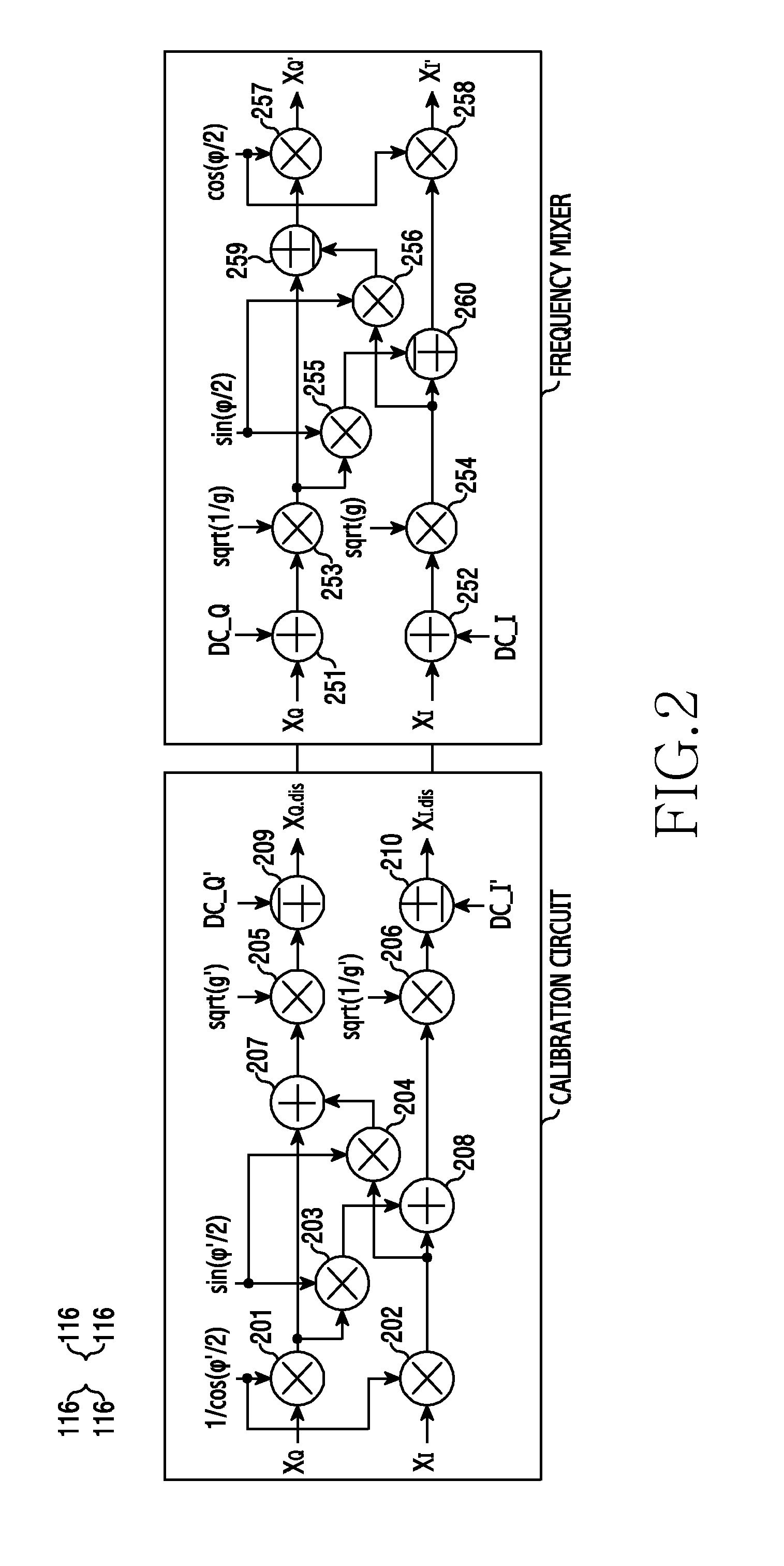
[0033]Various embodiments of the present disclosure are associated with calibration for suppressing an emission of a Local Oscillator (LO) signal component from a transmitter into the air (e.g. LO leakage suppression calibration or carrier suppression calibration), calibration for minimizing signal distortion caused by I / Q mismatch (e.g. I / Q...


PUM


Abstract

An electronic device for and method of determining a calibration code is provided. The electronic device includes a modem configured to receive a transmission signal, determine a calibration code that minimizes distortion of the transmission signal, and calibrate the distortion of the transmission signal using the calibration code.

Description

PRIORITY[0001]This application claims priority under 35 U.S.C. §119(a) and §120 to a U.S. Provisional Patent Application Serial filed on May 14, 2014 in the United States Patent and Trademark Office and assigned Ser. No. 61 / 996,846 and a Korean Patent Application filed on Jul. 23, 2014 in the Korean Intellectual Property Office and assigned Serial No. 10-2014-0093184, the entire contents of which are incorporated herein by reference.BACKGROUND[0002]1. Field of the Disclosure[0003]The present disclosure relates generally to a transceiver of an electronic device, and more particularly, to a calibration apparatus and method for minimizing distortion of a signal of a wireless transceiver.[0004]2. Description of the Related Art[0005]Technologies that use a frequency mixer to convert a baseband signal or an intermediate frequency signal into a Radio Frequency (RF) signal, or to convert an RF signal into a baseband signal or an intermediate frequency signal, have been widely utilized in th...

Claims


Application Information

Patent Timeline
Patent Type & Authority Applications(United States)
IPC IPC(8): H04B17/11H04B1/04
CPCH04B1/0475H04B17/11H03F1/3241H04B17/14H04B2001/0425
Inventor MYOUNG, SEONG-SIKCHOO, YOUNG-HWANHEO, SEUNG-CHAN
Owner SAMSUNG ELECTRONICS CO LTD
Learn More