A method and apparatus for de-noising data from a distance sensing camera

a technology of distance sensing camera and data de-noise, which is applied in the field of time-off-light camera system, can solve the problems of physical limitations of the sensors used, the inability to de-noise the distance map image, and the effect of noise limitation of the tof camera system

Active Publication Date: 2015-11-19
NOKIA TECHNOLOGLES OY
View PDF7 Cites 35 Cited by
  • Summary
  • Abstract
  • Description
  • Claims
  • Application Information

AI Technical Summary

Benefits of technology

[0025]According to another aspect of the application there is provided an apparatus comprising at least one processor and at least one memory including computer code for one or more programs, the at least one memory and the computer code configured with the at least one processor to cause the apparatus at least to: determine a phase difference between a light signal transmitted by a time of flight camera system and a reflected light signal received by at least one pixel sensor of an array of pixel sensors in an image sensor of the time of flight

Problems solved by technology

However, the distance map image can be corrupted with the effect of noise, whether it is random noise as a result of thermal noise in the charge coupled device or noise as a result of systematic errors in the measurement of the distance to the observed object.
For example, internal factors which can limit the capabilities of a ToF camera system may include the physical limitations of the sensors used such as inherent noise and resolution.
Other internal factors which can limit the capability of a ToF camera system can include the po

Method used


Image

  • A method and apparatus for de-noising data from a distance sensing camera
  • A method and apparatus for de-noising data from a distance sensing camera
  • A method and apparatus for de-noising data from a distance sensing camera

Examples


Embodiment Construction

[0010]The following embodiments aim to address the above problem.

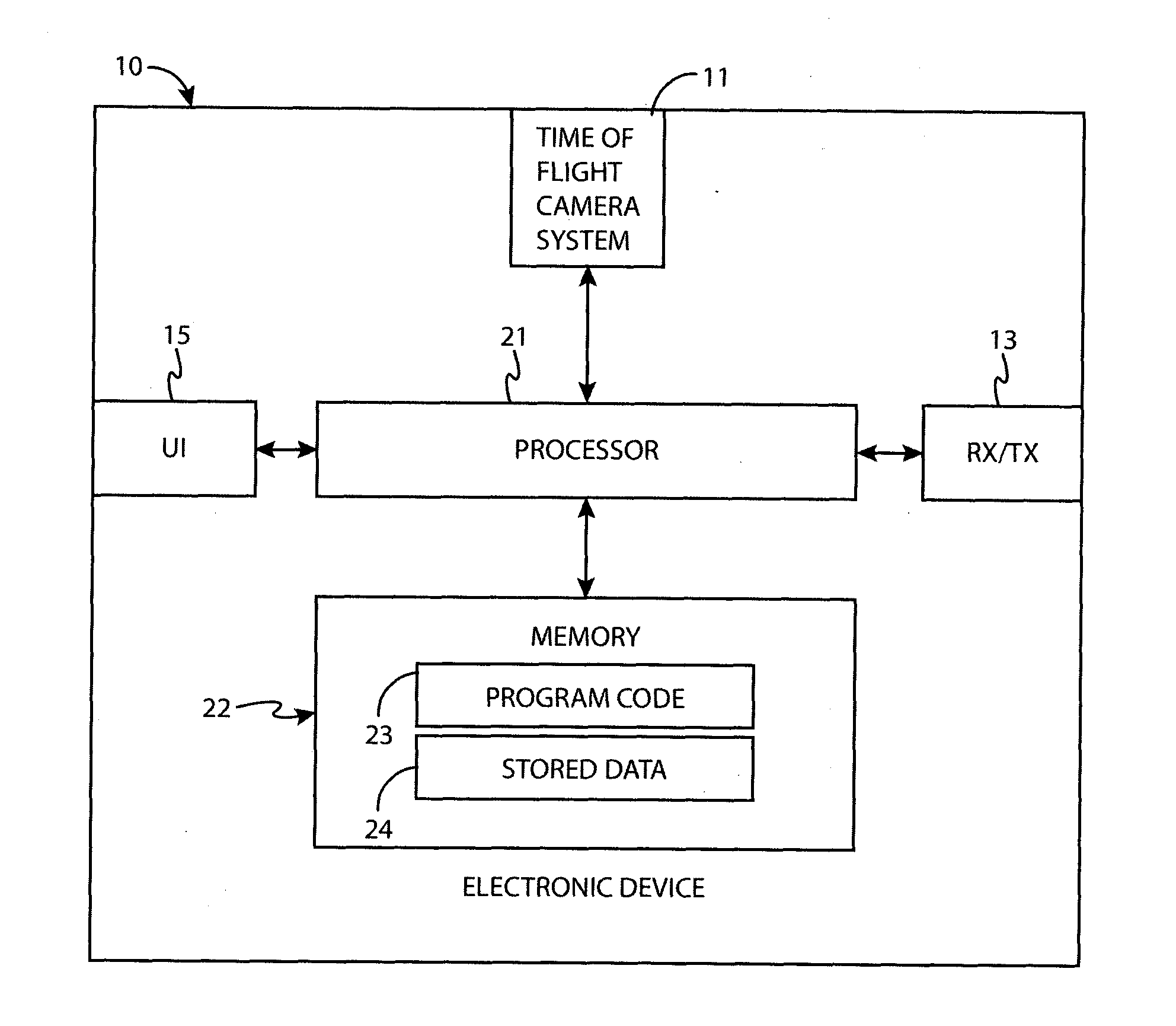
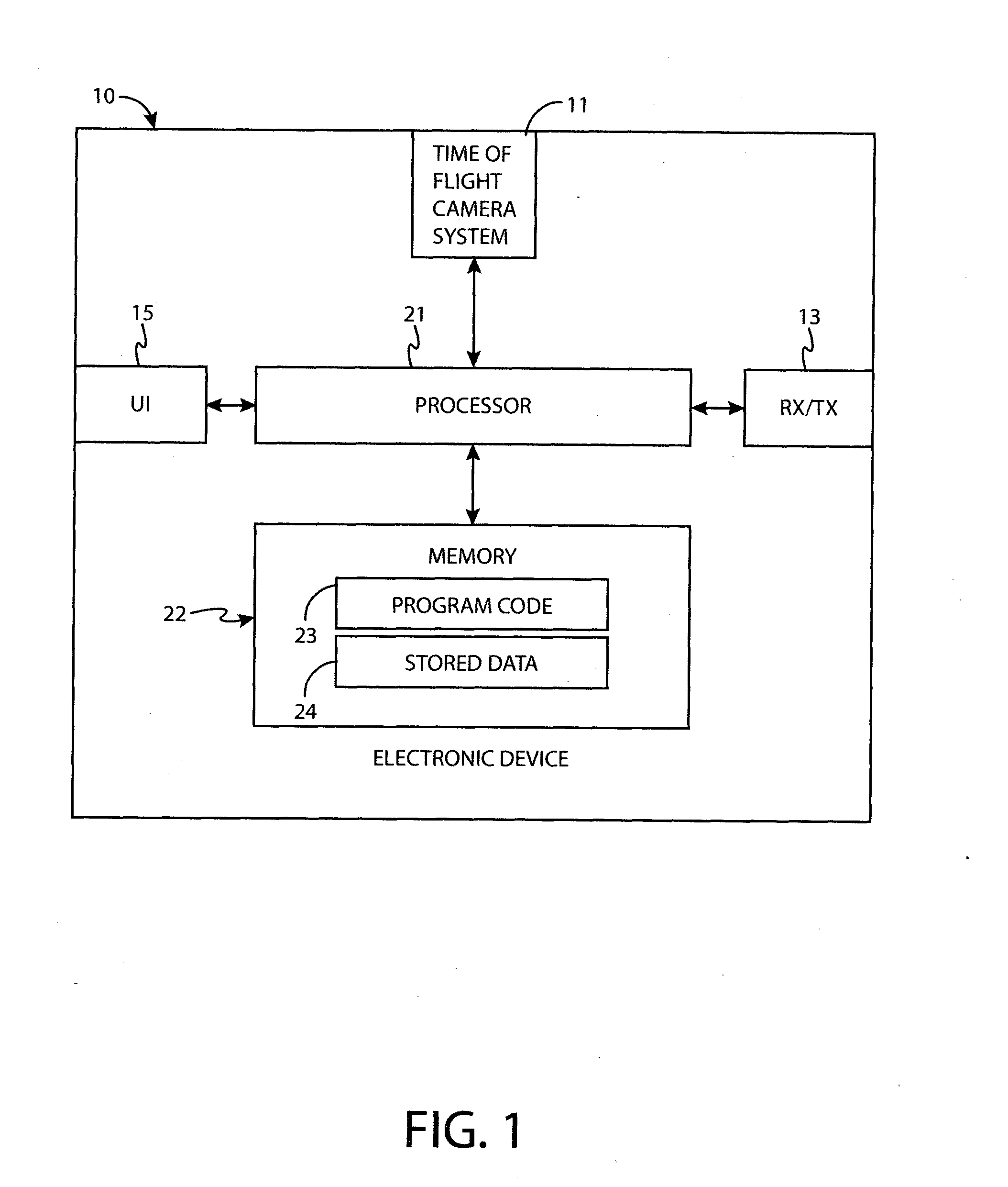
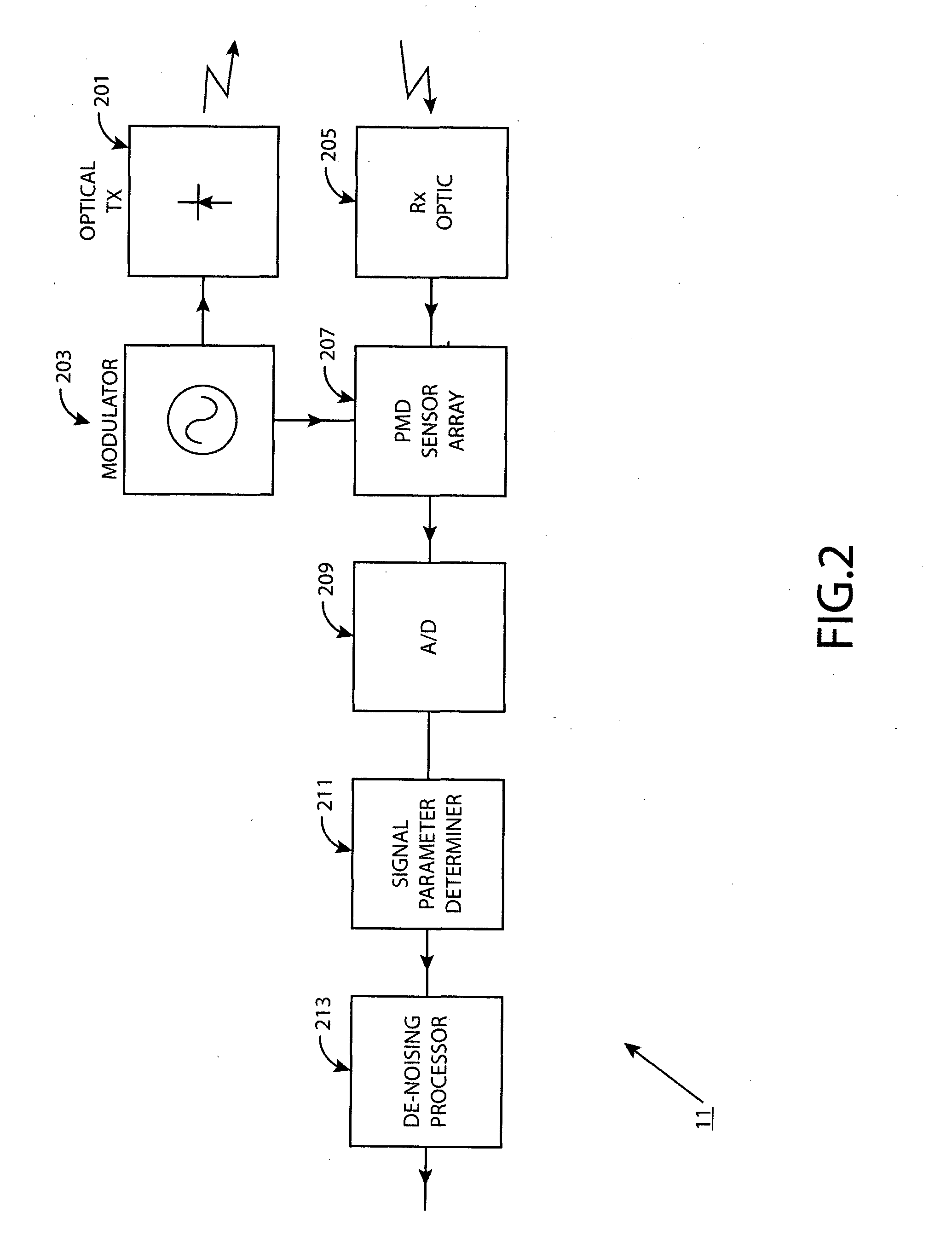
[0011]There is provided according to an aspect of the application a method comprising: determining a phase difference between a light signal transmitted by a time of flight camera system and a reflected light signal received by at least one pixel sensor of an array of pixel sensors in an image sensor of the time of flight camera system, wherein the reflected light signal received by the at least one pixel sensor is reflected from an object illuminated by the transmitted light signal; determining an amplitude of the reflected light signal received by the at least one pixel sensor; combining the amplitude and phase difference for the at least one pixel sensor into a combined signal parameter for the at least one pixel sensor; and de-noising the combined signal parameter for the at least one pixel sensor by filtering the combined parameter for the at least one pixel sensor.

[0012]The method may further comprise at least on...


PUM


Abstract

It is inter alia disclosed to determine a phase difference between a light signal transmitted by a time of flight camera system and a reflected light signal received by at least one pixel sensor of an array of pixel sensors in an image sensor of the time of flight camera system, wherein the reflected light signal received by the at least one pixel sensor is reflected from an object illuminated by the transmitted light signal (301); determine an amplitude of the reflected light signal received by the at least one pixel sensor (301); combine the amplitude and phase difference for the at least one pixel sensor into a combined signal parameter for the at least one pixel sensor (307); and de-noise the combined signal parameter for the at least one pixel sensor by filtering with a filter the combined parameter for the at least one pixel sensor (309).

Description

FIELD OF THE APPLICATION[0001]The present application relates to time-of-flight camera systems, and in particular the reduction of noise in the distance images from said time of flight camera systems.BACKGROUND OF THE APPLICATION[0002]Time-of-flight (ToF) cameras can sense distance or range to an object by emitting a pulse of modulated light signal and then measuring the time differential in the returning wave front.[0003]A ToF camera can comprise a light source such as a bank of light emitting diodes (LED) whereby a continuously modulated harmonic light signal can be emitted. The distance or range of an object from the light source can be determined by measuring the shift in phase (or difference in time) between the emitted and the reflected photons of light. The reflected photons can be sensed by the camera by the means of charge coupled device or the like.[0004]The phase shift (or phase delay) between the emitted and reflected photons is not measured directly. Instead a ToF camer...

Claims


Application Information

Patent Timeline
IPC IPC(8): H04N5/357H04N5/225H04N13/02G01S17/894
CPCH04N5/357H04N5/2256H04N13/0203G01S17/36G01S17/89G06T5/002G06T5/20G06T2207/10028G01S7/493H04N13/204G01S17/894H04N25/60H04N23/56
Inventor GEORGIEV, MIHAILGOTCHEV, ATANAS
Owner NOKIA TECHNOLOGLES OY
Why Eureka
Try Eureka