
Minimally invasive laparoscopic tissue removal device

a tissue removal and minimally invasive technology, applied in the field of laparoscopic operations, can solve the problems of device running across similar flaws, reducing the overall safety of the operation for physicians and patients, and straining and fatigu

Inactive Publication Date: 2015-11-26
UNIV OF SOUTH FLORIDA
View PDF4 Cites 8 Cited by
  • Summary
  • Abstract
  • Description
  • Claims
  • Application Information

AI Technical Summary

Benefits of technology

This patent is about a cover apparatus that can be used to control the exposure of a window on a mouthpiece of a morcellator. The cover can be a rotating outer sheath or a sliding outer sheath. The cover can be used to protect the window when the morcellator is not in use. The control apparatus can activate the morcellator by simultaneously rotating the jaws and auger. The technical effect of this patent is to provide a simple and effective way to control the exposure of the window on a mouthpiece of a morcellator during use.

Problems solved by technology

This prolonged period of time combined with repetitive hand actions, may cause strain and fatigue (Gale Encyclopedia of Medicine, 2008).
These problems lead to concerns in designing more ergonomic devices that may reduce the overall safety of the operation for physicians and patients.
Additionally, this device runs across similar flaws as previously described, such as remnants remaining in the body (particularly here where tissue must be broken down so much).
Thus, the sharp hook and blade are exposed to peripheral tissue, and the cutting window significantly limits the amount of tissue that can be cut in an efficient manner.
However, this device requires excessive manual effort from the surgical team, it would be easy for a portion of the tissue to become entirely cut off from the remaining tissue and be improperly left within the subject.
However, the device requires manual manipulation of the grasper to remove tissue from the body.
Additionally, the methodology of cutting, using a sawing motion, is inefficient and exposes surrounding tissue to being improperly cut.
However, the entirety of the mechanism of this device is manual and in particular relies on the grip of the surgeon's hand to actuate the cutting blade.
The device itself provides several points of inefficiency and an excess of energy consumption required from the surgical team.
Further, the device is designed to go through an abdominal port and thus is limited to the size of the port.
However, the device is limited to fifteen (15) mm and is inserted in an abdominal port to come in contact with the tissue.
The cover flap opens at an angle and thus the amount of tissue that can be efficiently cut is quite limited.
This creates a larger burden on the surgical team.
Additionally, there are many moving parts and complexities that may result in a malfunction of the device, particularly when deploying the bag within a body.
This device suffers many of the drawbacks previously explained through traditional morcellation techniques.
In particular, the tissue must be manually removed, and remnant tissue may remain within the body improperly.
The drawbacks of this device are that the tissue masses must be small enough for removal from the body, as the device does not morcellate the tissue, rather simply attempting to transport whole tissue outside of the body.
Major drawbacks of this device include peripheral or extraneous tissue being exposed to both the cutting blade and the corkscrew-like structure.
This may be particularly true when there are smaller pieces of tissue that need to be removed, and the corkscrew-like structure is incapable of engaging it.
The device provides an inefficient and dangerous manner of removing tissue from a body.
The devices currently used for laparoscopic surgeries lead to problems that are evident during an operation.
These problems include lack of proper cutting efficiency, safety concerns, and excessive scarring.
As indicated, a wide variety of different morcellation devices have been used in attempts to facilitate tissue removal, but there has been no growth for an effective cutting design.
Furthermore, where a definition or use of a term in a reference, which is incorporated by reference herein, is inconsistent or contrary to the definition of that term provided herein, the definition of that term provided herein applies and the definition of that term in the reference does not apply.

Method used


Image

  • Minimally invasive laparoscopic tissue removal device
  • Minimally invasive laparoscopic tissue removal device
  • Minimally invasive laparoscopic tissue removal device

Examples


example 1

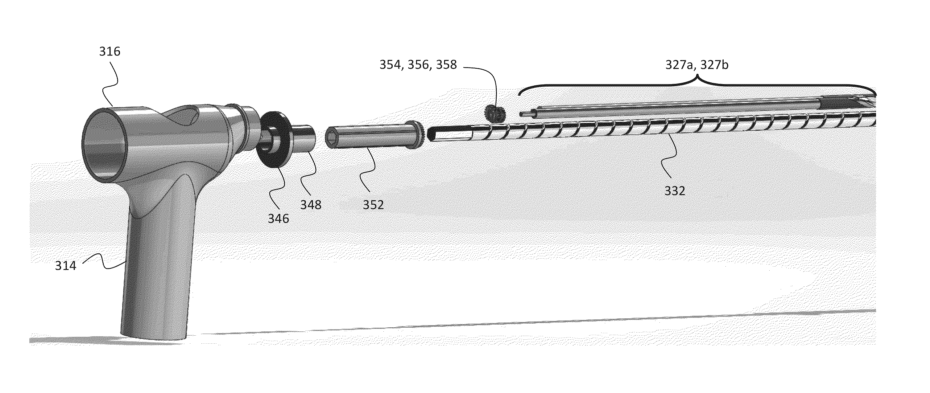
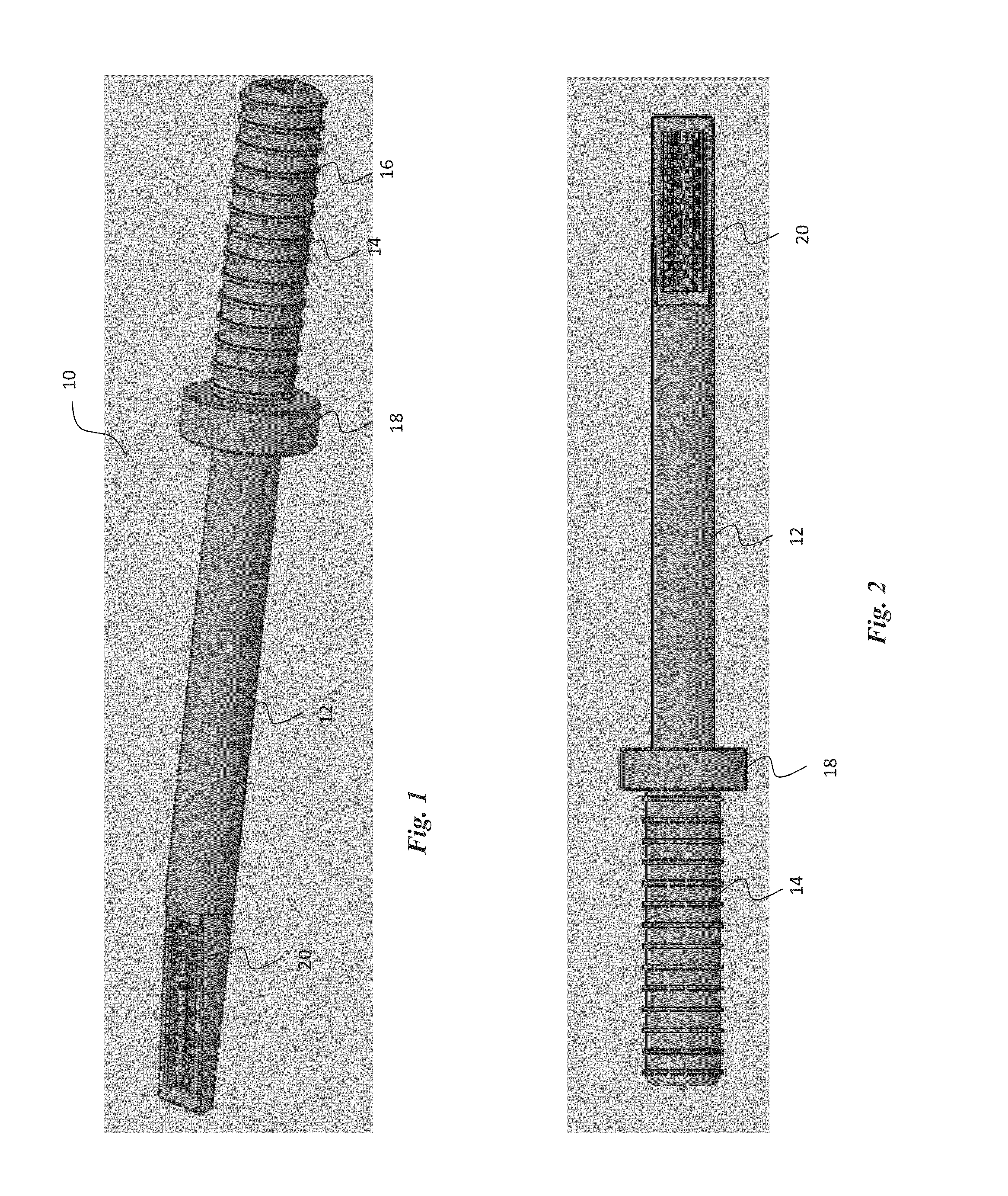
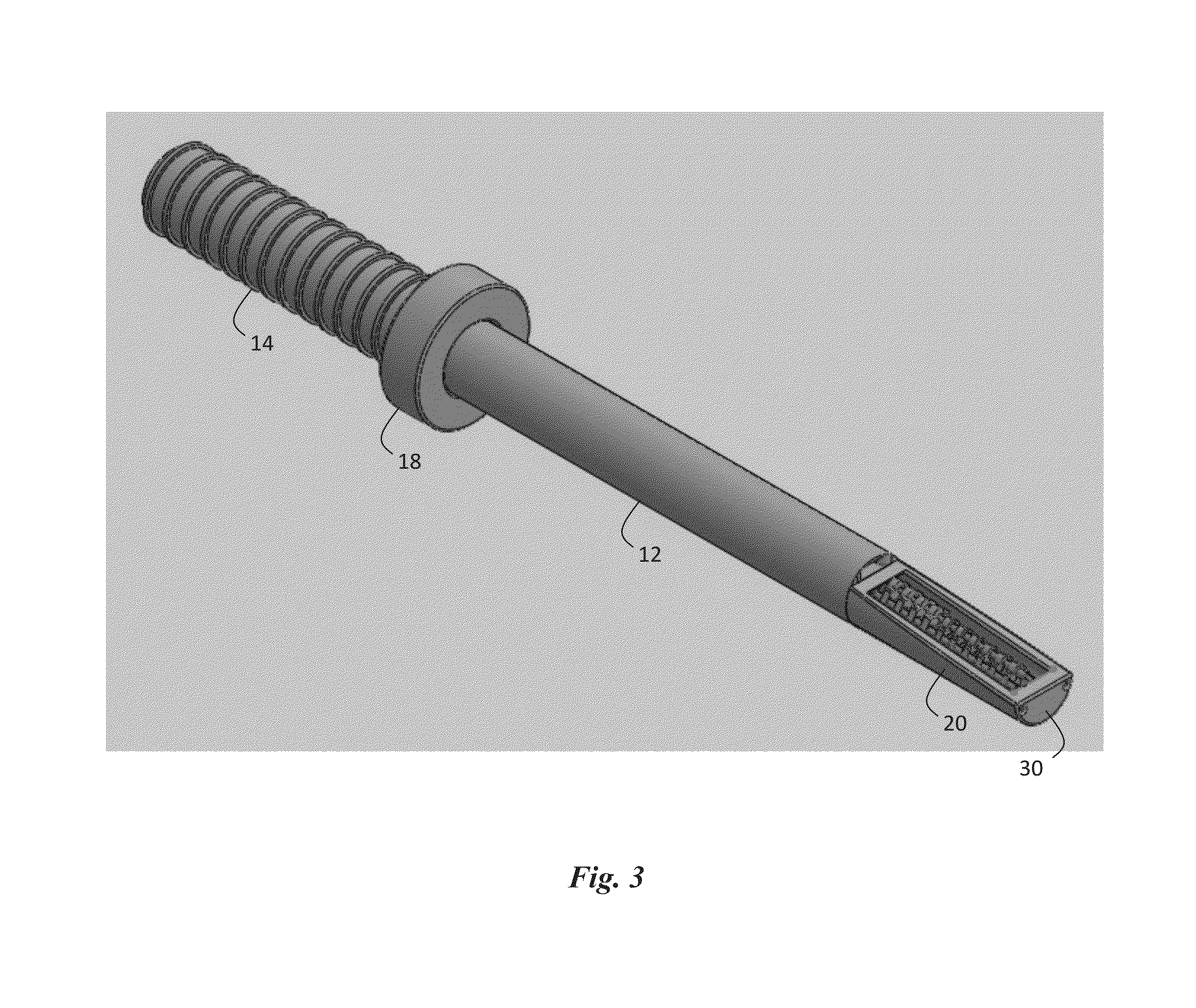
[0123]In an example, depicted in various aspects in FIGS. 1-15, the current invention is a laparoscopic morcellator denoted generally by the reference numeral 10. Morcellator includes three distinct aspects: handle 14, sheath 12 containing hollow lumen 13 (FIG. 12), and mouth 20 containing drive shafts 26 with interlocking teeth 24 attached thereto and disposed therearound (FIG. 15).

[0124]Handle 14 is typically cylindrical and adapted to conform to a user's hand, though any structure or conformation is contemplated. Grooves 16 may be disposed on handle 14 to provide an ergonomic design. Other types of ridges, grooves, finger indentations, and the like are contemplated by the current invention to enhance the comfort of the user and / or function of the overall structure.

[0125]Handle 14 may be connected to mouth 20 through auger 32 or other cylinder (e.g., cylinder 15) disposed within the hollow lumen of sheath 12. In an embodiment, handle 14 can be hollow, as indicated in FIGS. 13 and ...

example 2

[0150]Referring to FIG. 20, morcellator 100 includes handle 114, hand guard 118, hollow sheath 112, and auger 132 for cutting and transportation of tissue masses. This embodiment of the invention is fabricated with mouth 120 having a longitudinal axis parallel to that of sheath 112, rather than being beveled or otherwise angled as in mouth 20 of Example 1 seen in FIG. 4.

example 3

[0151]Referring to FIGS. 21-22, this embodiment of the invention is adapted for the vaginal port and referred to by the reference numeral 212. This embodiment is similar to the one depicted in FIGS. 1-15, but further includes outer sheath 212 slidably positioned in outer relation to the inner sheath (not shown) disposed therewithin. As seen in FIG. 22, outer sheath 212 has a diameter larger than the inner sheath and is slidably disposed so as to slide over mouth 220 to safely cover rotating blades 224 and auger 232. The outer diameter of morcellator 200 with outer sheath 212 can be about 30 mm, and the diameter of inner sheath (not shown) can be about 22 mm. This embodiment would not include a cup assembly that covers the cutting blades, such as that seen in FIG. 18.

[0152]Outer sheath 212 is retractable and safely houses cutting blades 224 and auger 232 and can be used as an adjustable blade barrier to allow an increase or decrease in surface area of the amount of blades 224 exposed...


PUM


Abstract

A minimally invasive laparoscopic tissue removal device, namely a morcellator. The device includes, from proximal end to distal end, a handle, handle guard, elongate sheath, and mouth, finally terminating in a safety tip. The elongate sheath and mouth are concentric, such that two elongate, rotating cutting / shredding blades / teeth and one elongate auger feed screw can be positioned along the length of the sheath and mouth. The teeth are opposingly disposed and staggered, such that contact with tissue mass grabs and pulls tissue inwards toward the auger, which transports the tissue proximally toward the outside of the patient's body. A motor unit and gear assembly can be coupled to the teeth and auger to drive rotation of the teeth and auger. A cup assembly can be disposed in overlying relation to the mouth for guiding the tissue mass towards the mouth. Various mechanisms of safely covering the mouth are contemplated as well.

Description

CROSS-REFERENCE TO RELATED APPLICATIONS[0001]This nonprovisional application is a continuation and claims priority to currently pending PCT application No. PCT / US2013 / 050085, entitled “Minimally Invasive Laparoscopic Tissue Removal Device”, filed Jul. 11, 2013, which claims priority to U.S. Provisional Application No. 61 / 760,892, entitled “Minimally invasive Laparoscopic Tissue Removal Device,” filed Feb. 5, 2013, and to U.S. Provisional Application No. 61 / 821,941, entitled “Minimally Invasive Laparoscopic Tissue Removal Device,” filed May 10, 2013, all of which are incorporated herein in their entireties.BACKGROUND OF THE INVENTION[0002]1. Field of the Invention[0003]This invention relates, generally, to laparoscopic operations. More particularly, it relates to a morcellator for laparoscopic hysterectomies[0004]2. Brief Description of the Prior Art[0005]Laparoscopic surgery, a type of minimally invasive surgery, has increased over the past 10 years due to a dramatic decrease in pos...

Claims


Application Information

Patent Timeline
IPC IPC(8): A61B17/32
CPCA61B17/32002A61B2017/320024A61B2017/00685
Inventor HART, STUART RICHARDESINHART, ERIK JAMESLYTLE, ADAM THOMASKAMSLER, DANIEL RYANDRAKE, III, CHARLES WILLIAMJUNAIDEEN, YASIN AHAMEDSIMOES, MARIO ALVES
Owner UNIV OF SOUTH FLORIDA
Learn More