Automatic Hammer

a technology of automatic hammer and hammer head, which is applied in the direction of nailing tools, packaging, stapling tools, etc., to achieve the effect of efficient installation of fasteners and minimal effor

Inactive Publication Date: 2015-11-26
STETSON JEREMY CHARLES +1
View PDF11 Cites 7 Cited by
  • Summary
  • Abstract
  • Description
  • Claims
  • Application Information

AI Technical Summary

Benefits of technology

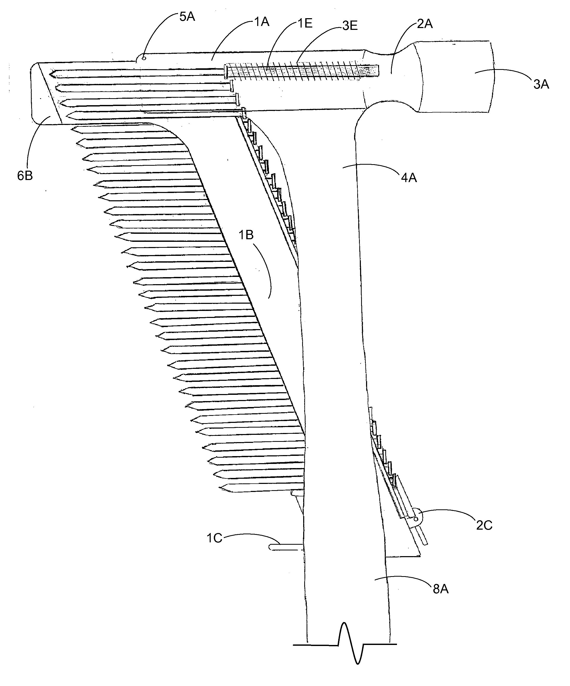
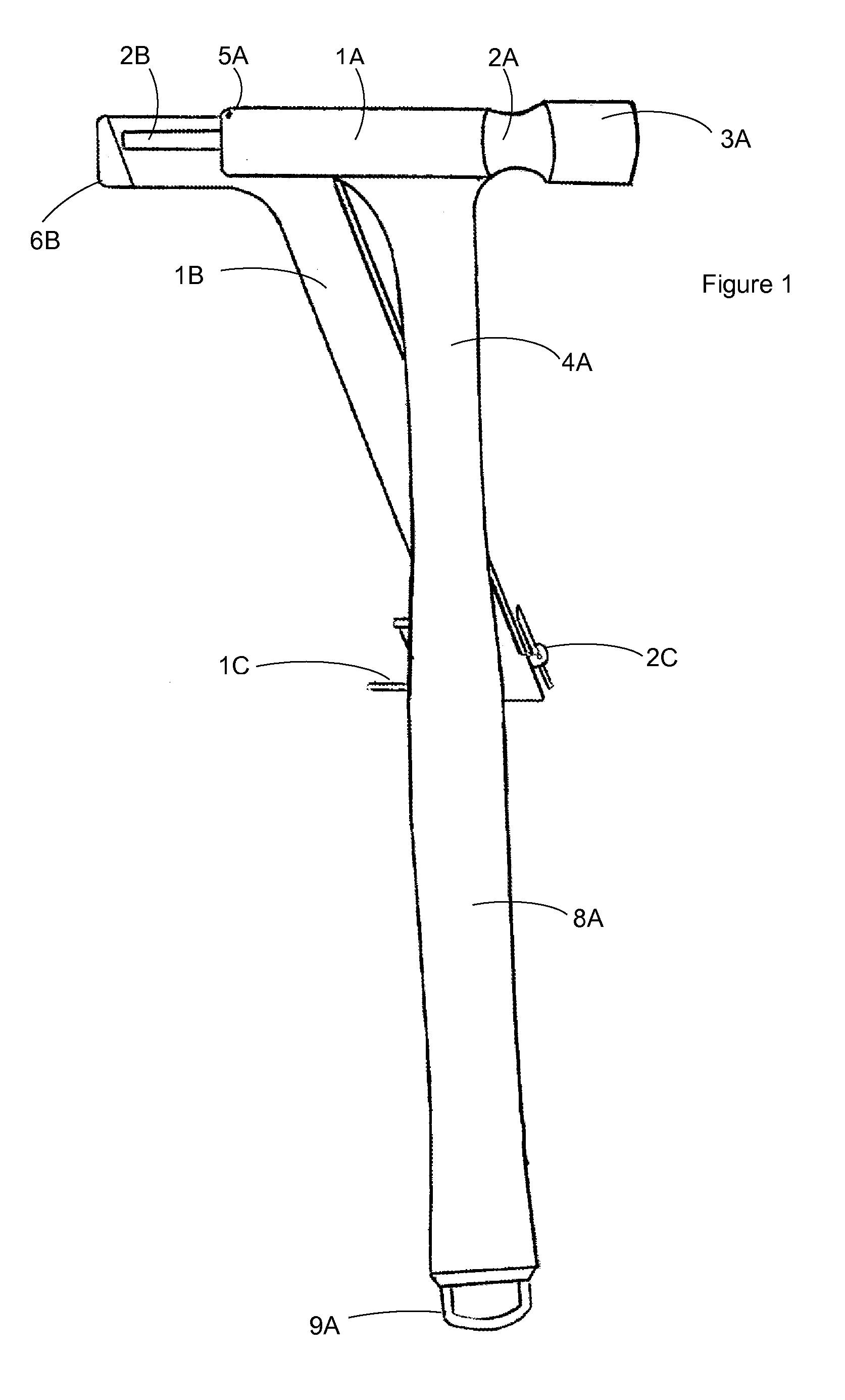
[0038]This is the next generation of the hammer. This is an auto-feed system of installing nails or modern fasteners used in any common facet in general construction ranging from but not limited to from rough carpentry, finish carpentry, and all other practical uses where a fastener is utilized. The system is designed to have an interchangeable magazine and nail driver to accommodate any nail size lending itself to the diversity of this product. This system will eliminate the need to manually hold a fastener during the act of installing said fastener as the entire operation can be done with one hand as opposed to modern techniques which includes the use of employing two hands; one hand to hold the fastener and the other hand to operate the hammer. This entire single operation is accomplished through the act of manually swinging the hammer system with enough force to actuate the magazines' lateral movement upon impact with the work surface, thereby driving the fastener into the intended position. Upon impact and installation of said fastener into the work surface, the subsequent nail from contained clip of nails will lift to position from a spring pressured spring follower resulting in a fully prepared ready for actuated impact of the Automatic Hammer.
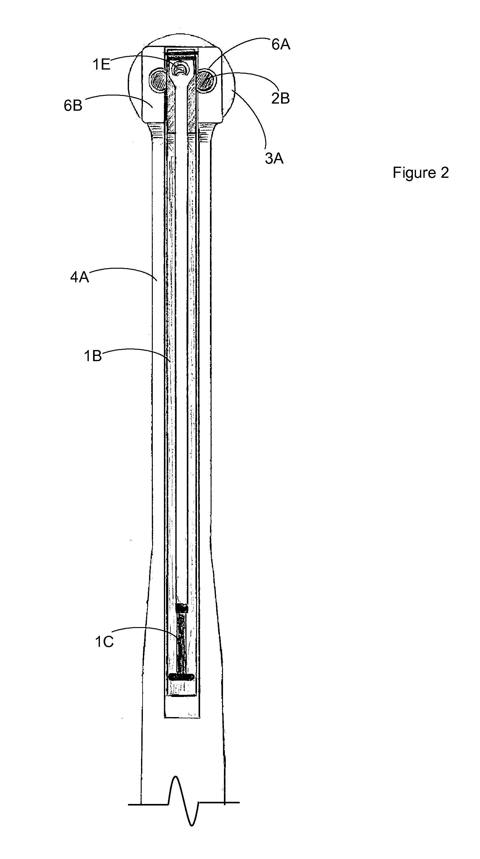
[0039]Upon installation of fasteners into the work surface, the advantage and intended use of the device is rotated 180° within the workhand. Once the hammer is rotated, the Automatic Hammer system is used to complete the installation of fastener through manual swinging and impact of the hammer head to fastener. The resulting installation of fastener does not release an additional nail on the opposite side of the hammer, due to the inertia device system. The inertia device system restrains all lateral movement of the nail magazine. The prevention of the nail magazine from lateral movement upon impact is due to the inertia device plunger extending into the inertia device notch contained within the hammer body. Once impact is complete, the inertia device plunger is reset to its natural position by the force of the inertia device spring into the inertia device housing.
[0040]This Automatic Hammer solves the inherent problem of utilizing two hands as opposed to the one-handed operation with this device. Secondly, the safety implications of one handed use resolves the issue of impact to user; from holding fastener with one hand and possible injury with hammer from other hand.
[0041]The object of this invention is to more efficiently install a fastener into a work surface with minimal effort as compared to currently used techniques due to the limited technologies of the basic hammer.

Problems solved by technology

The resulting installation of fastener does not release an additional nail on the opposite side of the hammer, due to the inertia device system.
Secondly, the safety implications of one handed use resolves the issue of impact to user; from holding fastener with one hand and possible injury with hammer from other hand.

Method used


Image

  • Automatic Hammer
  • Automatic Hammer
  • Automatic Hammer

Examples


Embodiment Construction

Process of Making Automatic Hammer

Forming the Automatic Hammer Body (1A), Inertia Device Plunger Stop Lever (2D), Nail Driver (1E), and Guide Rails (2B)

[0042]The head is made by a process called hot forging. A length of steel bar is heated to about 2,200-2,350° F. (1,200-1,300° C.). This may be done with open flame torches or by passing the bar through a high-power electrical induction coil.[0043]The hot bar may then be cut into shorter lengths, called blanks, or it may be fed continuously into a hot forge. The bar or blanks are positioned between two formed cavities, called dies, within the forge. One die is held in a fixed position, and the other is attached to a movable ram. The ram forces the two dies together under great pressure, squeezing the hot steel into the shape of the two cavities. This process is repeated several times using different shaped dies to gradually form the hammer head. The forging process aligns the internal grain structure of the steel and provides a much ...


PUM


Abstract

A framing hammer including an automatic feeding magazine supported within the hammerhead by guide rails with a self-loading magazine. Through the center of the upper portion of the hammer handle lies the self-loading reciprocating magazine. The top end of the magazine actuates due to the force of the impact of the tool through its natural operation. The magazine is inclined at 21° relative to the handle and is spaced in the center of the handle from the rear of the nail driving face. Structure is provided for individually driving a nail from a magazine contained row of commercially available 21° collated nails toward the rearward facing end of the hammerhead. Upon impact the tool dispenses and sets a nail up to a 1½″ into the work surface, upon disengagement the tool reciprocates to resets to its resting position whereupon the tool is ready to repeat the action.

Description

BACKGROUND OF THE INVENTION[0001]The Automatic Hammer is a combination of the common use hammer and pneumatic nail gun. A nail gun, nailgun, or nailer is a type of tool used to drive nails into wood or some other kind of material. The first nail gun used air pressure and was introduced to the market in 1950 to speed the construction of housing (Unknown, Nail Gun, n.d.).[0002]A nail gun uses the most popular sort of nail-loading mechanism. The nails are connected together in a long strip. This nail strip loads into the gun's magazine, which feeds into the “barrel” of the gun. Springs in the base of the magazine push the nail strip into the barrel. When the hammer comes down, it separates the first nail from the strip, driving it out of the gun and into the wood. When the hammer is cocked back, the springs push the next nail into position (Harris, 2001).[0003]Framing hammers, used for framing wooden houses, are heavy duty rip hammers with a straight claw. The hammer heads typically we...

Claims


Application Information

Patent Timeline
Patent Type & Authority Applications(United States)
IPC IPC(8): B25D1/00B25D1/14B25C5/16B25C1/02
CPCB25D1/005B25C1/02B25C5/1686B25C5/1665B25D1/14B25C1/005
Inventor STETSON, JEREMY CHARLESMAY, JOSHUA PHILLIP
Owner STETSON JEREMY CHARLES
Why Eureka
Try Eureka