Retractor pretensioner assembly

a pretensioner and retraction technology, applied in the direction of belt retractors, vehicle safety belts, vehicle components, etc., can solve the problems of low resistance, the weight of the series of balls required for a full pretensioning stroke, and the corresponding cost of supplying multiple metallic balls with strict tolerances

Active Publication Date: 2015-11-26
AUTOLIV ASP INC
View PDF2 Cites 53 Cited by
  • Summary
  • Abstract
  • Description
  • Claims
  • Application Information

AI Technical Summary

Benefits of technology

[0007]The present invention provides a seatbelt pretensioning retractor assembly. The assembly includes a housing adapted for being mounted to a vehicle structure; a tube having an arcuate and curved shape having a first end in fluid communication with a gas generator and a second end in fluid communication with an interior cavity of the housing; a sprocket rotatably mounted to the housing and fixedly coupled to a spindle adapted for taking up seatbelt webbing during pretensioning, the sprocket having a plurality of vanes; at least one driving element disposed within the tube and translatable through the tube in a first direction toward the sprocket in response to an actuation by the generator; and a seal member disposed between the generator and the at least one driving element. The tube includes a constriction portion having an opening smaller than the width of adjacent portions of the tube and disposed adjacent the exit. The constriction portion is sized to permit the driving element to pass therethrough and to prevent the seal member from passing therethrough.

Problems solved by technology

One issue with pretensioners using a series of metallic balls is the weight of the series of balls required for a full pretensioning stroke, as well as the corresponding cost of supplying multiple metallic balls with strict tolerances.
Another issue with pretensioners is known as a low resistance condition, where the driving elements will reach an end of stroke without experience substantial resistance.
This can occur if there is excessive slack in the seatbelt webbing.
In these cases, the low resistance results in a lower amount of backpressure from the driving elements.
Reduced sealing ability can cause gas to leak from the tube around the series of balls.
A further issue with pretensioners is the need to maintain the retractor and the seatbelt webbing in a locked condition at the end of the pretensioning stroke.
However, this adds weight and cost.

Method used


Image

  • Retractor pretensioner assembly
  • Retractor pretensioner assembly
  • Retractor pretensioner assembly

Examples


Embodiment Construction

[0033]The following description is merely exemplary in nature and is not intended to limit the present disclosure or its application or uses.

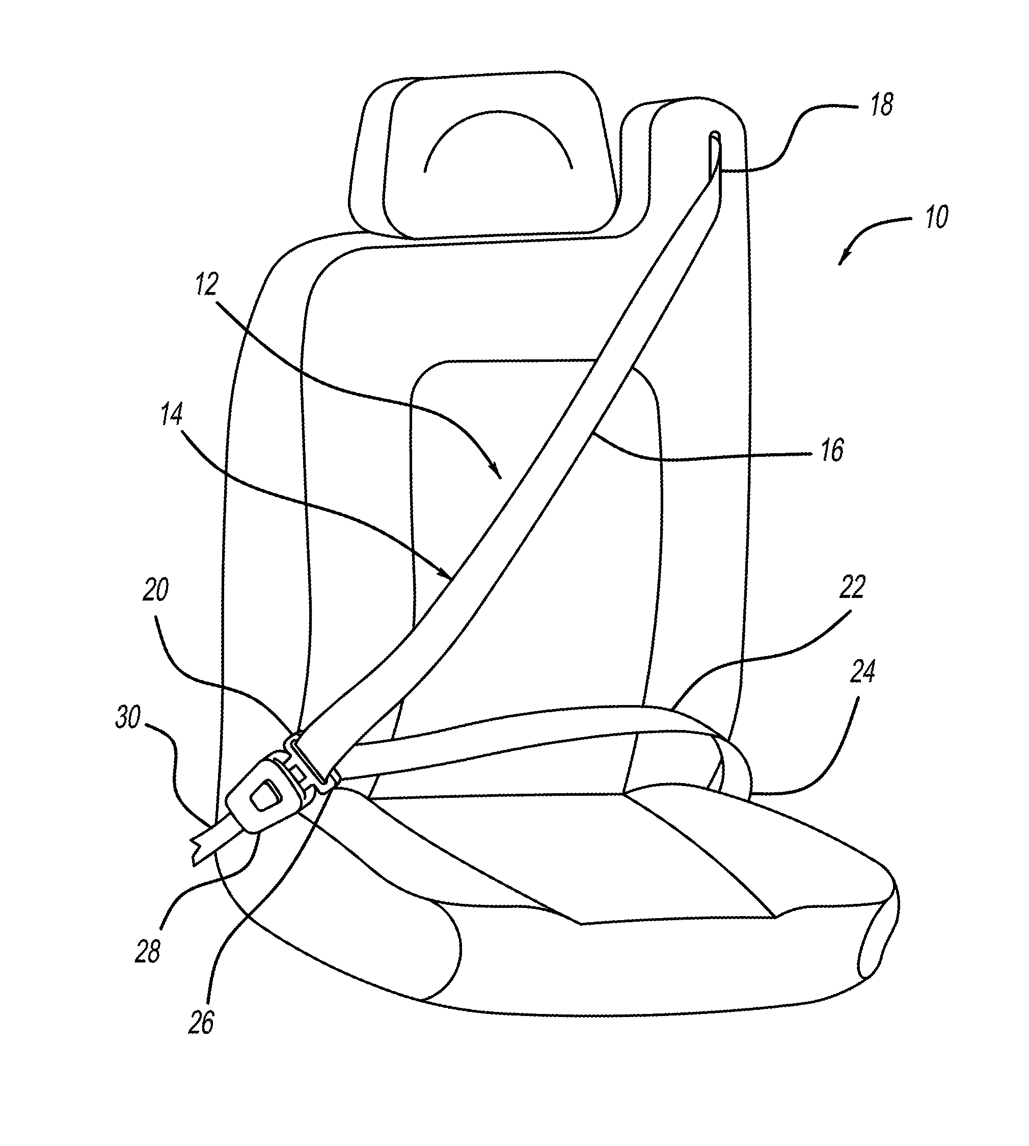
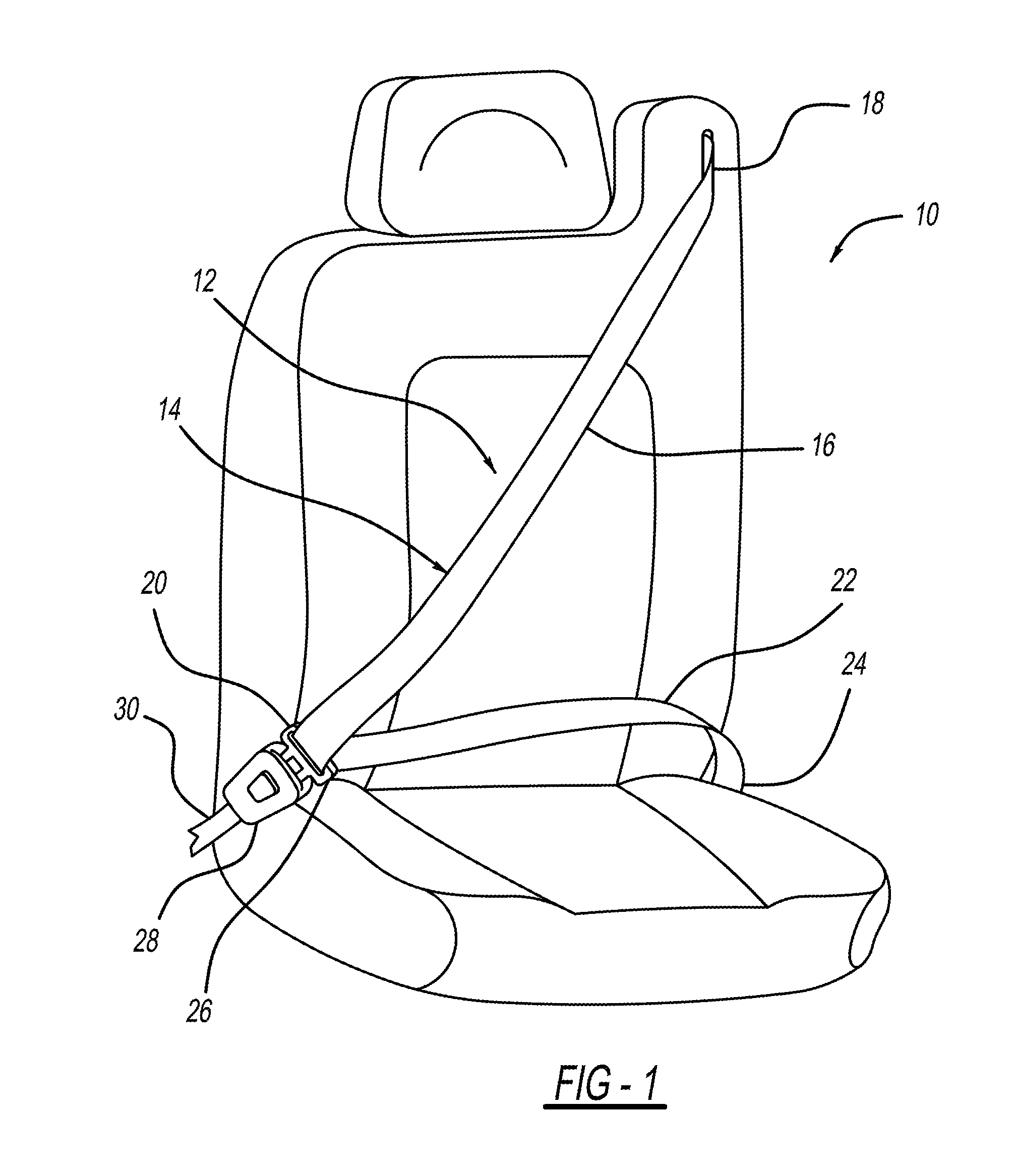
[0034]Referring now to the drawings, FIG. 1 shows a vehicle seat 10 and a seat belt assembly 12. The seat belt assembly 12 includes a seat belt webbing 14 having a shoulder belt portion 16 extending from an upper guide loop or anchorage 18 to a latch plate 20 and a lap belt portion 22 extending from the latch plate 20 to an anchorage 24. The latch plate 20 can include a loop portion 26 through which the webbing 14 extends. The latch plate 20 is able to be inserted into a seat belt buckle 28 to lock and unlock the seat belt assembly 12. A seat belt buckle cable 30, either directly or in cooperation with other components, secures the seat belt buckle 28 to a portion of the vehicle frame. It will be appreciated that other manners of attaching the seat belt webbing 14 to vehicle could also be used, including variations on the latch plate 26 and the...


PUM


Abstract

A pretensioner assembly for motor vehicle belt restraint systems is provided. The pretensioner assembly includes a tube in fluid communication with a gas generator and a driving element disposed therein that travels in a first direction in response to actuation of the gas generator. The tube includes a constriction disposed adjacent an exit of the tube. The constriction allows the driving element to pass but prevents a seal member disposed between the generator and the driving element from passing. The constriction provides backpressure on the seal member causing the seal member to expand radially outward. The system can also include a slug member disposed between the seal member and the driving element.

Description

FIELD OF THE INVENTION[0001]The present invention relates generally to seatbelt restraint devices for restraining an occupant of a vehicle, and more particularly, to devices for pretensioning a seatbelt.BACKGROUND OF THE INVENTION[0002]Seatbelt restraint systems for restraining an occupant in a vehicle seat play an important role in reducing occupant injury in vehicle crash situations. Seatbelt restraint systems of the conventional so-called “3-point” variety commonly have a lap belt section extending across the seat occupant's pelvis and a shoulder belt section crossing the upper torso, which are fastened together or are formed by a continuous length of seatbelt webbing. The lap and shoulder belt sections are connected to the vehicle structure by anchorages. A belt retractor is typically provided to store belt webbing and may further act to manage belt tension loads in a crash situation. Seatbelt restraint systems which are manually deployed by the occupant (so-called “active” type...

Claims


Application Information

Patent Timeline
Patent Type & Authority Applications(United States)
IPC IPC(8): B60R22/46
CPCB60R22/4628B60R2022/4642
Inventor GRAY, MARK F.KOHLNDORFER, KENNETH H.
Owner AUTOLIV ASP INC
Why Eureka
Try Eureka