
Nozzle for a plastic container and plastic container for pressurized gases

a technology for plastic containers and nozzles, which is applied in the direction of gas/liquid distribution and storage, containers, pliable tubular containers, etc., can solve the problems of increasing the cost of the end product, and the complexity of the productive process, and the limitations of the pressure level of the gas to be stored and the type of solution

Inactive Publication Date: 2015-11-26
FIBRASYNTHETICA DO BRASIL
View PDF2 Cites 10 Cited by
  • Summary
  • Abstract
  • Description
  • Claims
  • Application Information

AI Technical Summary

Benefits of technology

The present invention provides a nozzle that can be easily and tightly attached to a pre-formed wall portion in plastic material of a container for containing gases under high pressures. This allows for a stronger and more reliable attachment compared to prior art solutions. Additionally, the invention provides a method for reliably and hermetically sealing the nozzle and wall portion by compressing the sealing means and tightening the nut. The technical effects of the invention include improved strength, reliability, and durability of the attachment of containers to nozzles, as well as improved sealing of the attachment.

Problems solved by technology

With the purpose of incorporating the metallic nozzles in said containers of plastic material, the known constructive solutions have proved to be very complex or inadequate to ensure the necessary and reliable tightness between the nozzle, in the form of a metallic tubular insert, and the hollow body of the plastic container, when the pressures in the interior of the latter reach high values, such as, for example, those superior to about 5 kg / cm2.
Such operation increases the complexity of the productive process, as well as the cost of the end product.
Besides requiring especial cares for shaping the peripheral flange and injecting the end wall portion on the flange of the tubular insert, this type of solution presents limitations regarding the pressure level of the gas to be stored and the type of construction applied to the wall that defines the hollow body of the container.
In the applications in which a high gas storage pressure is required, the solutions which use, as the only plastic-metal fixation means, the molding and anchorage of the adjacent end wall portion on the peripheral flange, are not adequate for the containers whose hollow body is formed from wall portions defined, usually by injection, in only one plastic material, such as, for example, high density polyethylene.

Method used


Image

  • Nozzle for a plastic container and plastic container for pressurized gases
  • Nozzle for a plastic container and plastic container for pressurized gases
  • Nozzle for a plastic container and plastic container for pressurized gases

Examples


Embodiment Construction

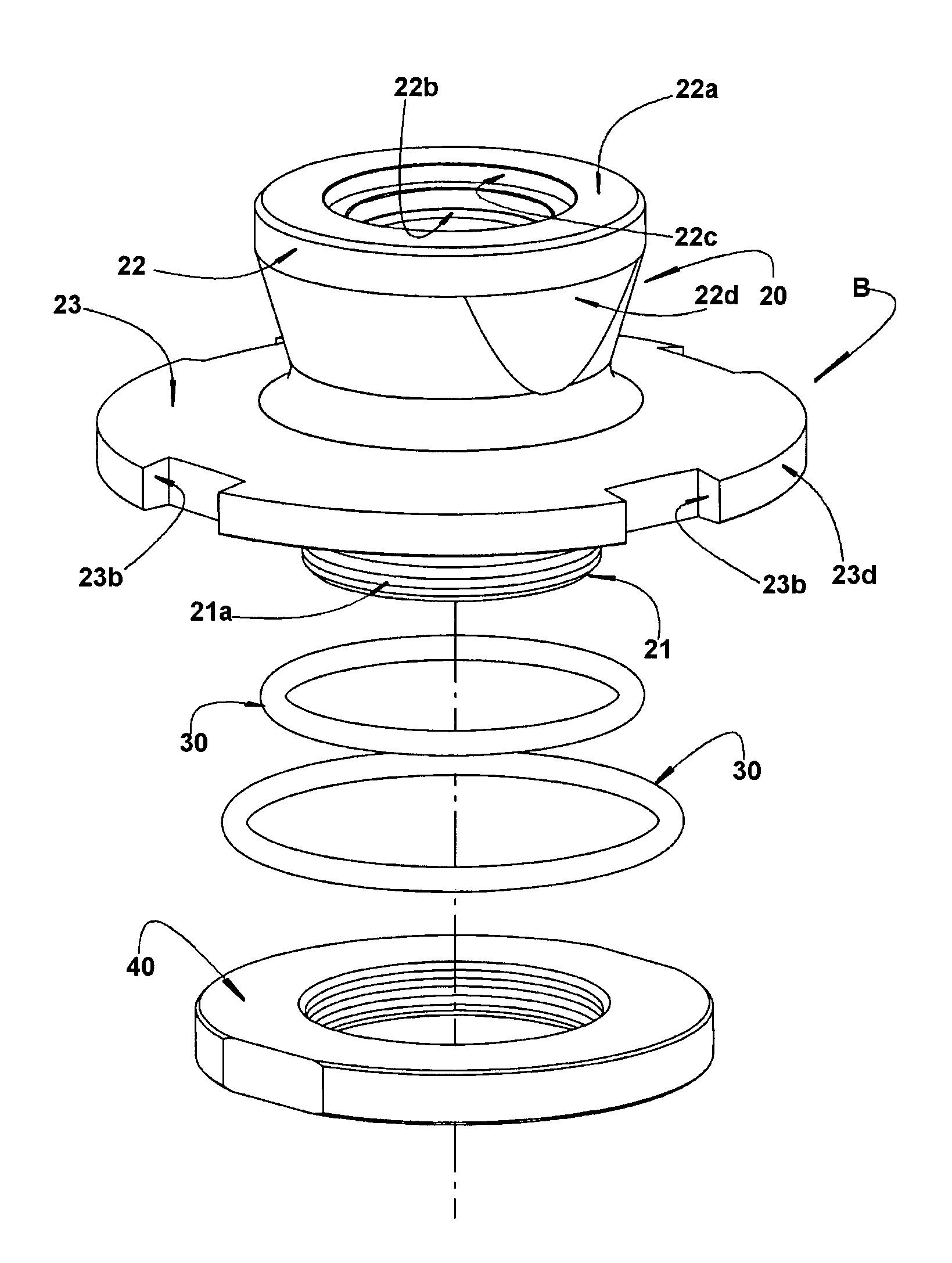
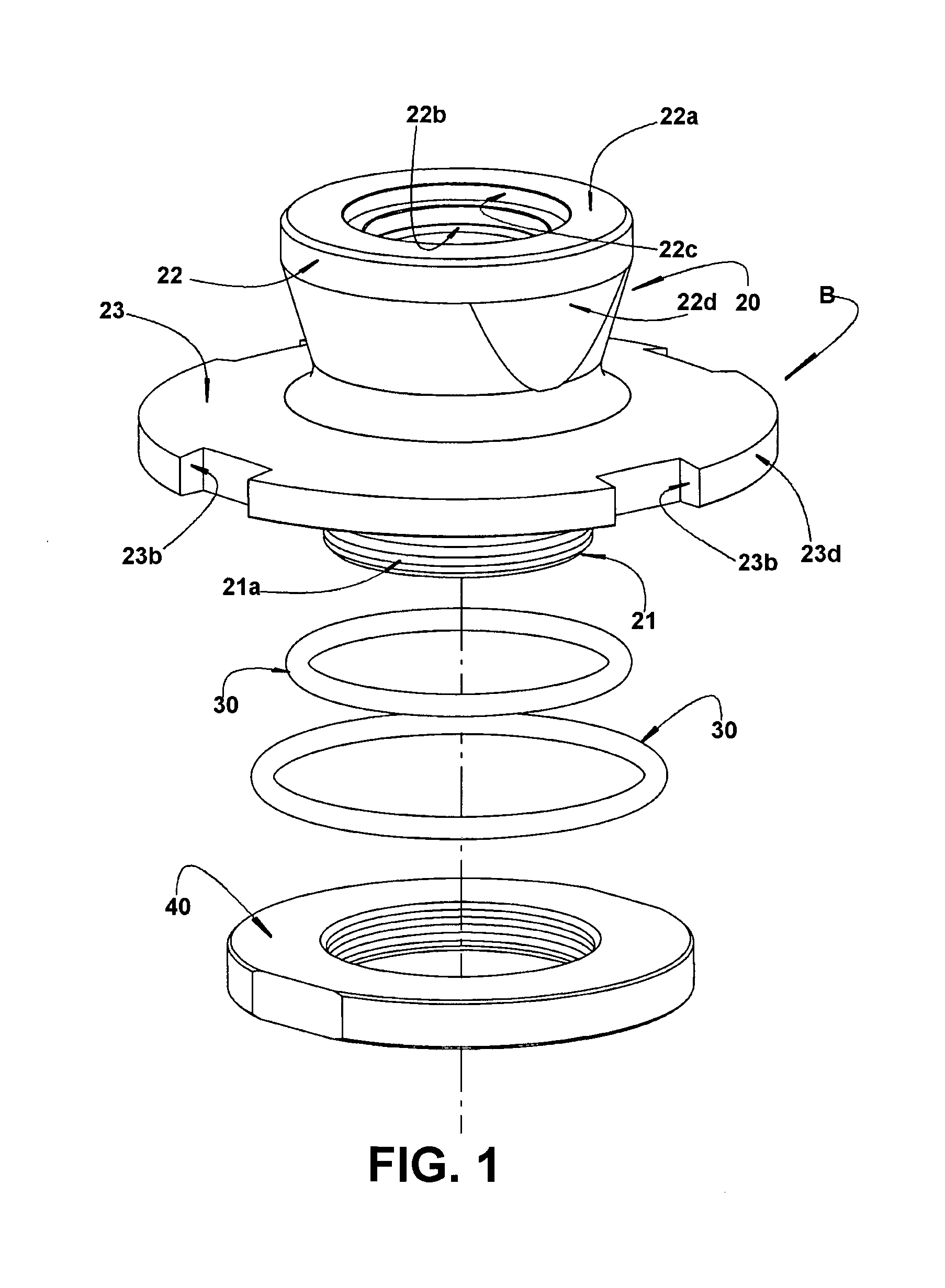
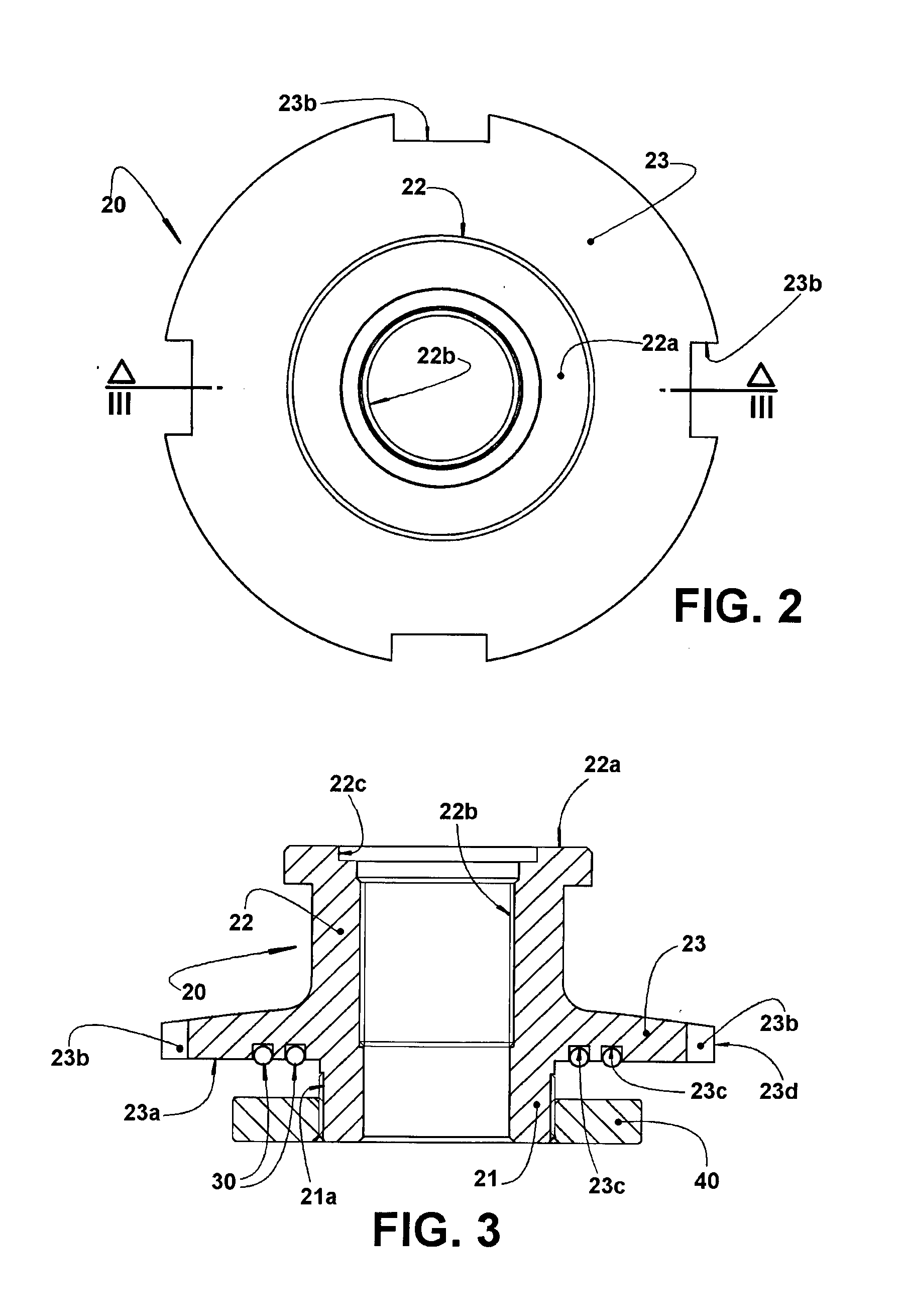
[0022]As already previously mentioned and illustrated in the appended drawings, the nozzle B of the invention is constructed in metallic material, generally steel, to be fixed to a container formed in plastic material, for example high density polyethylene. The container presents a hollow body 10 having a wall 11 formed in plastic material, impermeable to the gas to be stored and including an end wall portion 12 provided with an access opening A, communicating the exterior with the interior of the hollow body 10.

[0023]According to the invention, the nozzle B takes the form of a metallic tubular insert 20 which comprises a mounting portion 21, provided with an external thread 21a and which is fitted through the access opening A of the end wall portion 12, so as to project to the interior of the hollow body 10. The metallic tubular insert 20 further incorporates a nozzle portion 22, having a free end 22a projecting to the outside of the hollow body 10, and an external peripheral flang...


PUM

PropertyMeasurementUnit
Shapeaaaaaaaaaa

Abstract

The container has an end wall portion (12) provided with an access opening (A) in which is affixed a nozzle (B) in the form of a metallic tubular insert (20) comprising: a mounting portion (21) fitted in the access opening (A); a nozzle portion (22); an external peripheral flange (23), having an annular face (23a) in which are adapted annular sealing means (30); and a nut (40) adapted around the mounting portion (21) and pressing the end wall portion (12) against the annular sealing means (30) of the annular face (23a) of the flange (23). The end wall portion (12) may be preformed in a single piece with an annular wall portion or fixed to the latter, and provided, in both constructions, with a median opening (13,51) which defines the access opening (A) of the container.

Description

FIELD OF THE INVENTION[0001]The present invention refers to a nozzle to be incorporated, as a metallic tubular insert, in a container in the form of a vessel or bottle, having its hollow body constructed in plastic material such as, for example, high density polyethylene, generally having a cylindrical shape and used for storage and transportation of pressurized gases, such as oxygen, natural gas, hydrogen or other gases for domestic, commercial or industrial applications. The invention is also related to a plastic container provided with at least one nozzle, in the form of a metallic tubular insert, for mounting the usual valves for containing and releasing the gas which is stored, generally under pressure, in the interior of the hollow body of the container.BACKGROUND OF THE INVENTION[0002]It is known in the art the containers made of single or composite plastic material, and which present, in relation to the metallic containers, several advantages, such as great weight reduction,...

Claims


Application Information

Patent Timeline
IPC IPC(8): F17C1/16F17C13/00
CPCF17C1/16F17C13/00F17C2201/056F17C2260/011F17C2203/0617F17C2203/066F17C2205/0305F17C2201/0109F17C2201/0119F17C2201/0123F17C2209/2118F17C2209/221F17C2209/234F17C2221/011F17C2221/012F17C2221/033F17C2223/0123F17C2223/035F17C2223/036F17C2270/05F17C2270/07Y02E60/32
Inventor IWATA, EDUARDO KUNIOKI
Owner FIBRASYNTHETICA DO BRASIL
Learn More