Ultrasonic diagnostic apparatus

a diagnostic apparatus and ultrasonic technology, applied in the field of ultrasonic diagnostic equipment, can solve problems such as preventing the identification of optimal sound velocity, and achieve the effect of optimal sound velocity

Active Publication Date: 2015-12-03
GE MEDICAL SYST GLOBAL TECH CO LLC
View PDF8 Cites 5 Cited by
  • Summary
  • Abstract
  • Description
  • Claims
  • Application Information

AI Technical Summary

Benefits of technology

[0006]According to the technique described in Japanese Patent No. 3642607, however, in case that a structure such as a bone or a blood vessel is contained in a region subjected to analysis of the spatial frequency, comparatively low spatial frequency components corresponding to the structure are dominant. For example, in case that a structure extending in a transverse direction is contained, comparatively low spatial frequency components corresponding to the structure are dominant in a result of spatial frequency analysis in a horizontal direction. Consequently, even when the value of the sound velocity in biological tissue changes, an effect thereof on the result of spatial frequency analysis may be relatively small, causing concern that the variance in the result of spatial frequency analysis may be rather unchanged. This may prevent identification of an optimal sound velocity.

Problems solved by technology

This may prevent identification of an optimal sound velocity.

Method used


Image

  • Ultrasonic diagnostic apparatus
  • Ultrasonic diagnostic apparatus
  • Ultrasonic diagnostic apparatus

Examples


first embodiment

[0078]Next, a variation of the first embodiment will be described based on a flow chart in FIG. 12. First, at Step S11, a B-mode image BI is displayed, as in Step S1 described above. Upon display of the B-mode image BI, an operator makes an input for defining a plurality of regions of interest R1, R2, R3 at the operating section 7. This input causes the region-of-interest defining section 82 to define the regions of interest R1, R2, R3 in the B-mode image BI, as shown in FIG. 13.

[0079]In this variation, again, the regions of interest R1, R2, R3 may be automatically defined by the region-of-interest defining section 82.

[0080]Next, at Step S12, reception beamforming and transmission beamforming are performed based on each of the sound velocities S1, S2, S3, S4, S5, as in Step S2 described above.

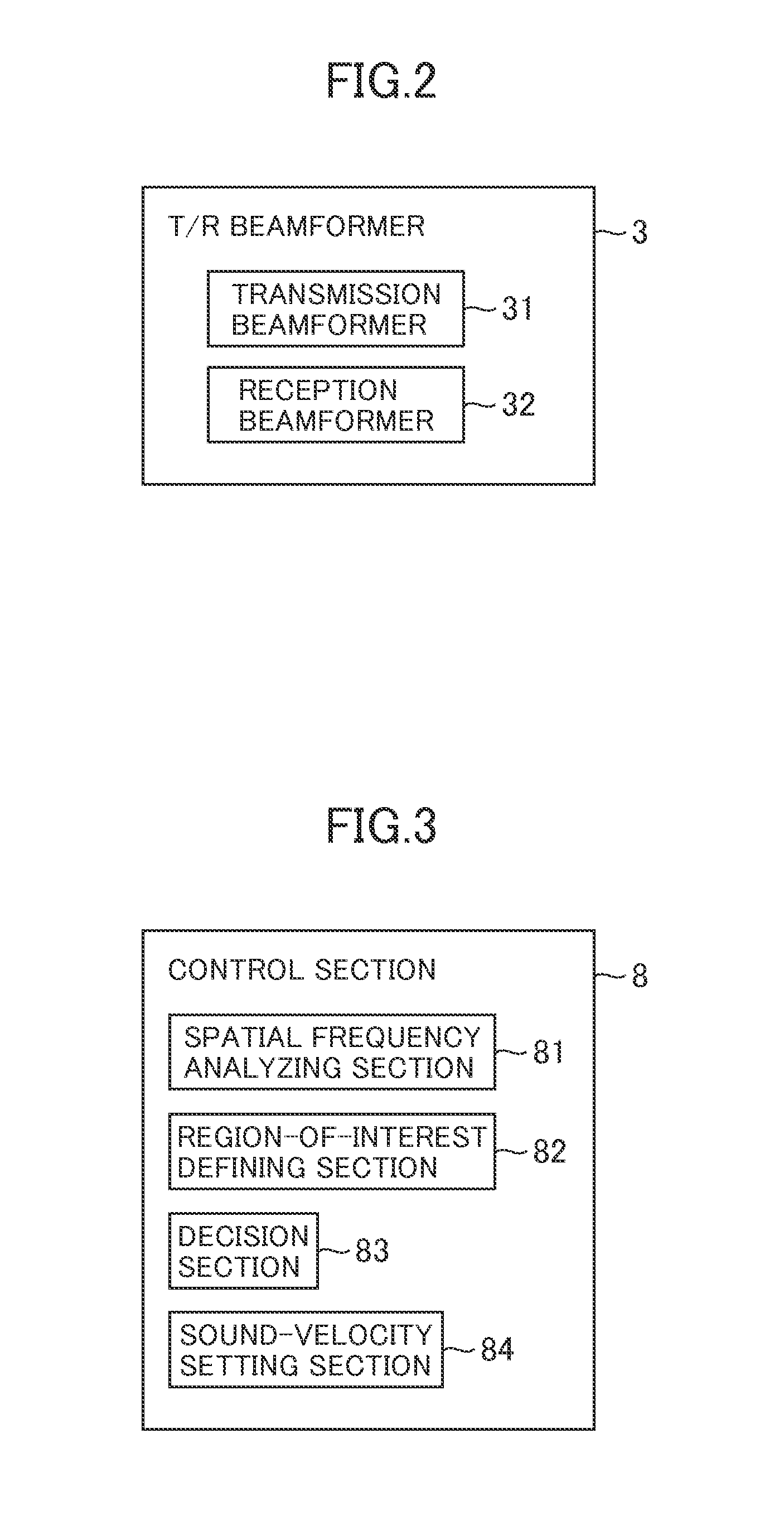
[0081]Next, at Step S13, the spatial frequency analyzing section 81 applies spatial frequency analysis to each of the data D1-D5, as in Step S13 described above, for each of the regions of inte...

second embodiment

[0102]Next, a variation of the second embodiment will be described. In this variation, the control section 8 loads thereon a program stored in the storage section 9 and executes functions of the spatial frequency analyzing section 81, region-of-interest defining section 82, decision section 83, and sound-velocity setting section 84, and besides, executes functions of a movement detecting section 85 and a position correcting section 86 by the program, as shown in FIG. 15. The movement detecting section 85 represents an exemplary embodiment of the movement detecting section in the present invention. The position correcting section 86 represents an exemplary embodiment of the position correcting section in the present invention.

[0103]An operation of the variation will now be described. In the present variation, movement of a portion in which the region of interest R is defined in a subject is detected by the movement detecting section 85, and based on a detected amount of movement, the...


PUM


Abstract

An ultrasonic diagnostic apparatus is characterized in comprising: an ultrasonic probe for transmitting/receiving ultrasound to/from a subject; a reception beamformer for applying reception beamforming to ultrasonic echo signals obtained by the ultrasonic probe based on a plurality of different sound velocities; a spatial frequency analyzing section 81 for applying spatial frequency analysis to each of data obtained by the reception beamforming based on each of the plurality of different sound velocities; and a sound-velocity setting section 84 for setting a sound velocity corresponding to one of the results of spatial frequency analysis corresponding respectively to the plurality of different sound velocities that has a highest intensity for a given spatial frequency, as optimal sound velocity in the reception beamforming.

Description

FIELD OF THE INVENTION[0001]Embodiments of the present invention relate to an ultrasonic diagnostic apparatus for conducting transmission / reception of ultrasound to / from a subject.BACKGROUND[0002]An ultrasonic diagnostic apparatus transmits ultrasound to biological tissue in a subject by an ultrasonic probe. Echo signals of the ultrasound are received by the ultrasonic probe, and an ultrasonic image based on the echo signals is produced.[0003]The ultrasonic probe comprises a plurality of ultrasonic vibrators. Transmission / reception of ultrasound is conducted in each of the plurality of ultrasonic vibrators. An echo signal received at each ultrasonic vibrator is input to a reception beamformer. The reception beamformer applies reception beamforming to the echo signal received at each ultrasonic vibrator. The reception beamforming is phased-addition processing involving delaying the echo signals received at the ultrasonic vibrators and adding the resulting signals together.[0004]A del...

Claims


Application Information

Patent Timeline
Patent Type & Authority Applications(United States)
IPC IPC(8): A61B8/08A61B8/14A61B8/00
CPCA61B8/5207A61B8/4444A61B8/54A61B8/461A61B8/469A61B8/4254A61B8/14A61B8/5269G01S7/52049G10K11/346
Inventor KATO, SEIHASHIMOTO, HIROSHI
Owner GE MEDICAL SYST GLOBAL TECH CO LLC
Why Eureka
Try Eureka