Aerodynamic fairing

Active Publication Date: 2015-12-03
AIRBUS OPERATIONS (SAS)
View PDF16 Cites 1 Cited by
  • Summary
  • Abstract
  • Description
  • Claims
  • Application Information

AI Technical Summary

Benefits of technology

[0005]An object of the invention is to at least partially overc

Problems solved by technology

These temperatures bring about deformations as a result of thermal expansions of the fairing, thus disrupting the aerodynamic qualities thereof In particular, the thermal protection floor is subjected to a primary flow of the turbo engine at high temperature (in the order of 60

Method used


Image

  • Aerodynamic fairing
  • Aerodynamic fairing
  • Aerodynamic fairing

Examples


Embodiment Construction

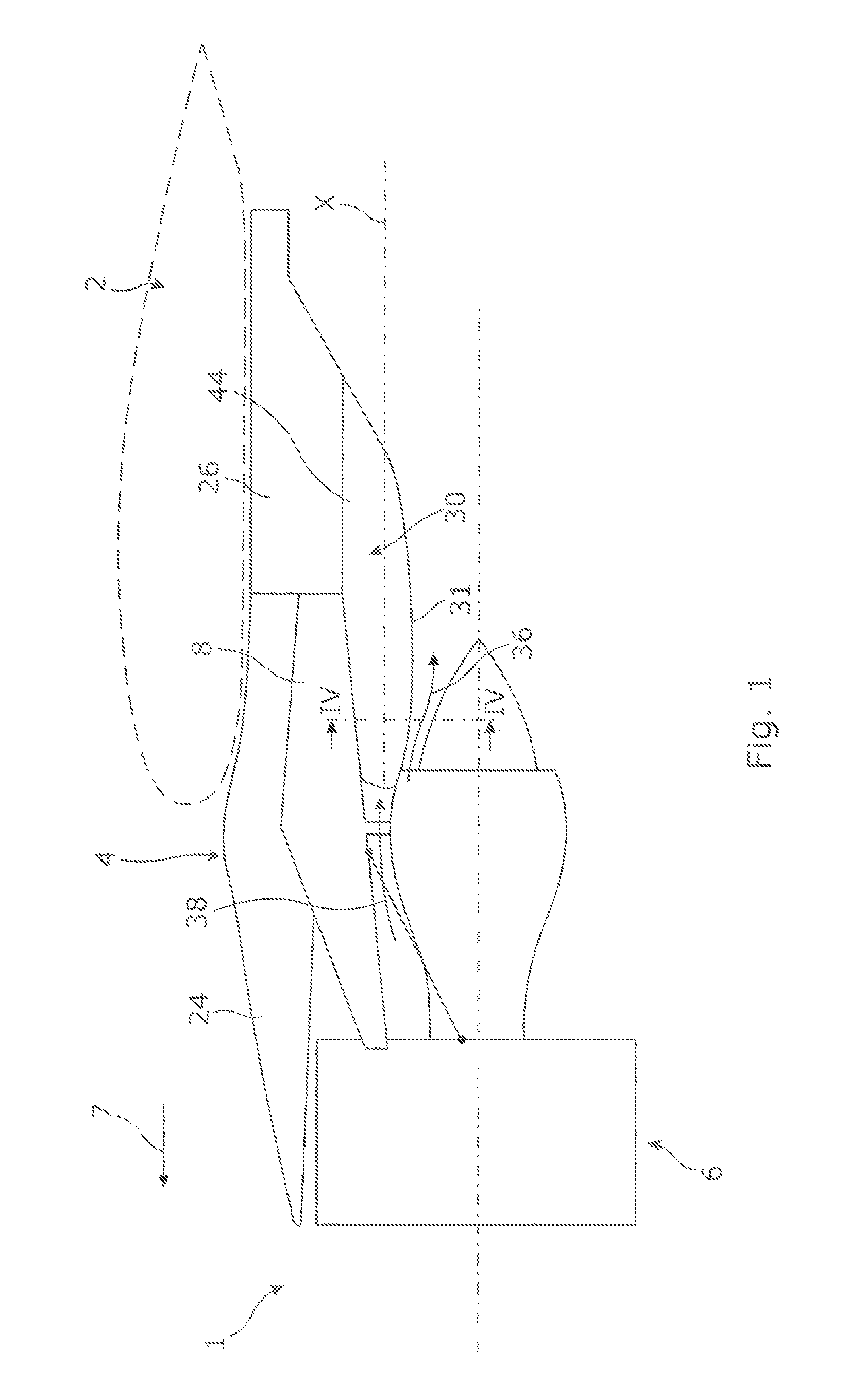
[0022]With reference to FIG. 1, an engine unit 1 which is fixed below a wing 2 of an aircraft is illustrated. The engine unit comprises a pylon 4 and a turbo engine 6, for example, a turbo reactor, which is secured to the wing 2 via the pylon 4.

[0023]The pylon 4 comprises in known manner a rigid structure 8, which is also called a primary structure, which allows the turbo reactor 6 to be supported via known means.

[0024]Furthermore, the pylon 4 comprises secondary structures of the fairing type.

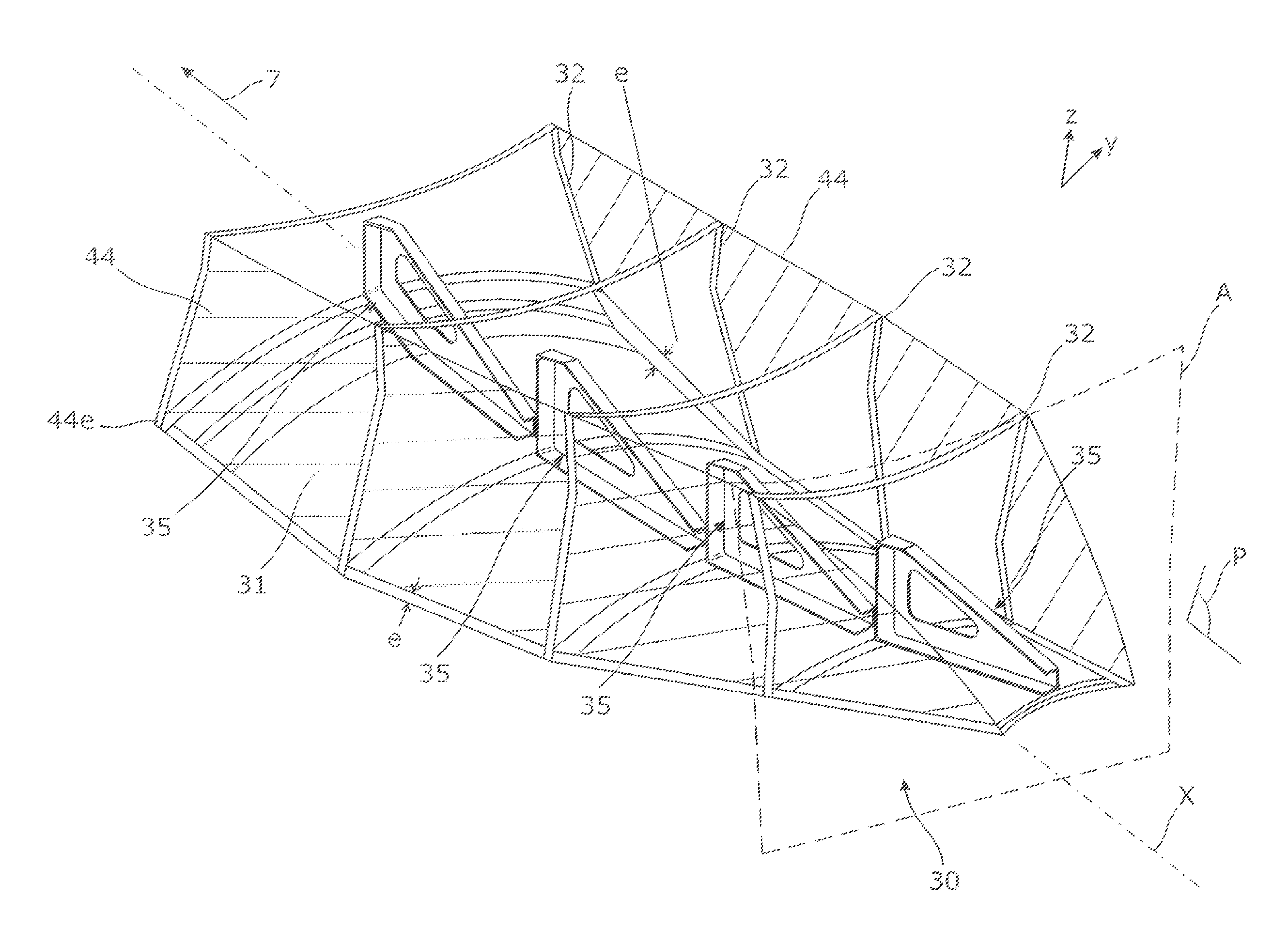
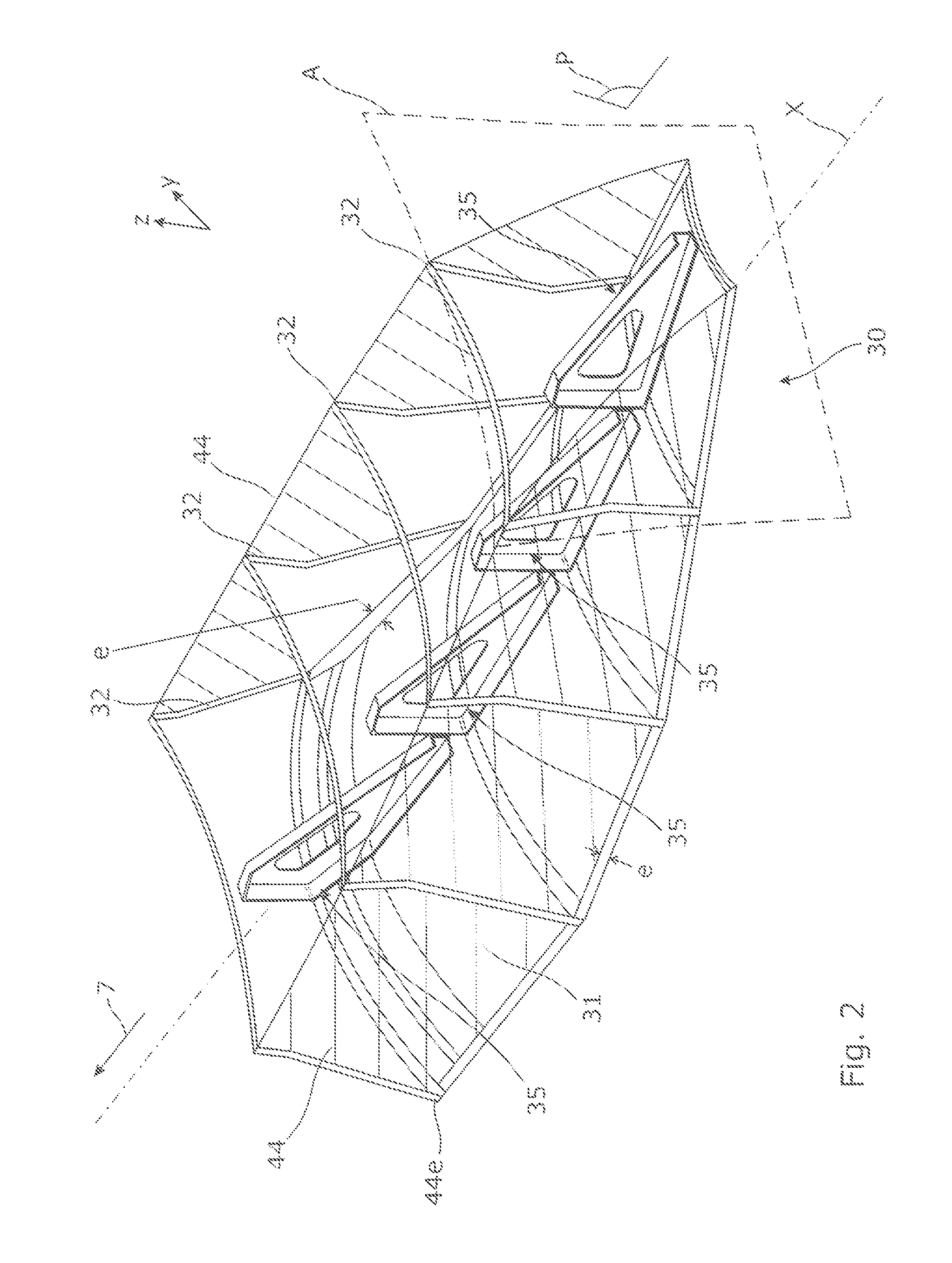
[0025]The secondary structures of the pylon 4 include in particular a front aerodynamic structure 24, a rear aerodynamic structure 26 and a rear aerodynamic fairing 30, which is also called an APF or thermal shield. The terms “front” and “rear” are intended to be considered relative to a direction of advance of the aircraft encountered following the thrust applied by the turbo reactor 6, this direction being illustrated schematically by the arrow 7.

[0026]As illustrated in FIGS. 2 to 4, the rea...


PUM


Abstract

An aerodynamic fairing whose floor has absolutely no contact with respect to the lateral panels over the entire length of the fairing along the longitudinal axis. A free space e is provided between the floor and the lower edge of each panel. There is a longitudinal mechanical gap between the floor and each of the lateral panels. The absence of any rigid mechanical connection between the floor and the lateral panels allows the transfer of the thermomechanical stresses from the floor to the lateral panels and therefore preventing the deformation of the fairing.

Description

CROSS-REFERENCES TO RELATED APPLICATIONS[0001]This application claims the benefit of the French patent application No. 1361555 filed on Nov. 25, 2013, the entire disclosures of which are incorporated herein by way of reference.BACKGROUND OF THE INVENTION[0002]The present invention relates to an aerodynamic fairing of the rear portion of an aircraft pylon which is also referred to as an “aft pylon fairing” or APF.[0003]Such an aerodynamic fairing is known in particular from the document U.S. Pat. No. 4,712,750. In this document, the aerodynamic fairing is in the form of a casing which comprises two lateral panels which are assembled together by means of frames or transverse inner reinforcement ribs which are spaced apart from each other along the longitudinal axis of the fairing, and a thermal protection floor which is fixed, on the one hand, to the lateral panels and, on the other hand, to the transverse inner ribs with which the floor is in contact.[0004]In a position for use, such...

Claims


Application Information

Patent Timeline
IPC IPC(8): B64D27/26
CPCB64D27/26B64D29/02
Inventor PEYRUSEIGT, FRANCOISGACHES, THIERRYKALETA, MATHIEUVOYER, NICOLAS
Owner AIRBUS OPERATIONS (SAS)
Why Eureka
Try Eureka