

Garment processing apparatus
a technology for processing equipment and garments, applied in drying machines, lighting and heating equipment, furnaces, etc., can solve the problems of laundry treatment equipment that needs to supply unnecessarily excessive energy to the heat exchanger, low heat exchange efficiency, and air discharged from the laundry accommodation unit through only a portion of the heat exchanger, so as to achieve accurate determination of dryness of laundry and maximally prevent impurities contained
Active Publication Date: 2015-12-03
LG ELECTRONICS INC
View PDF21 Cites 21 Cited by
- Summary
- Abstract
- Description
- Claims
- Application Information
AI Technical Summary
Benefits of technology
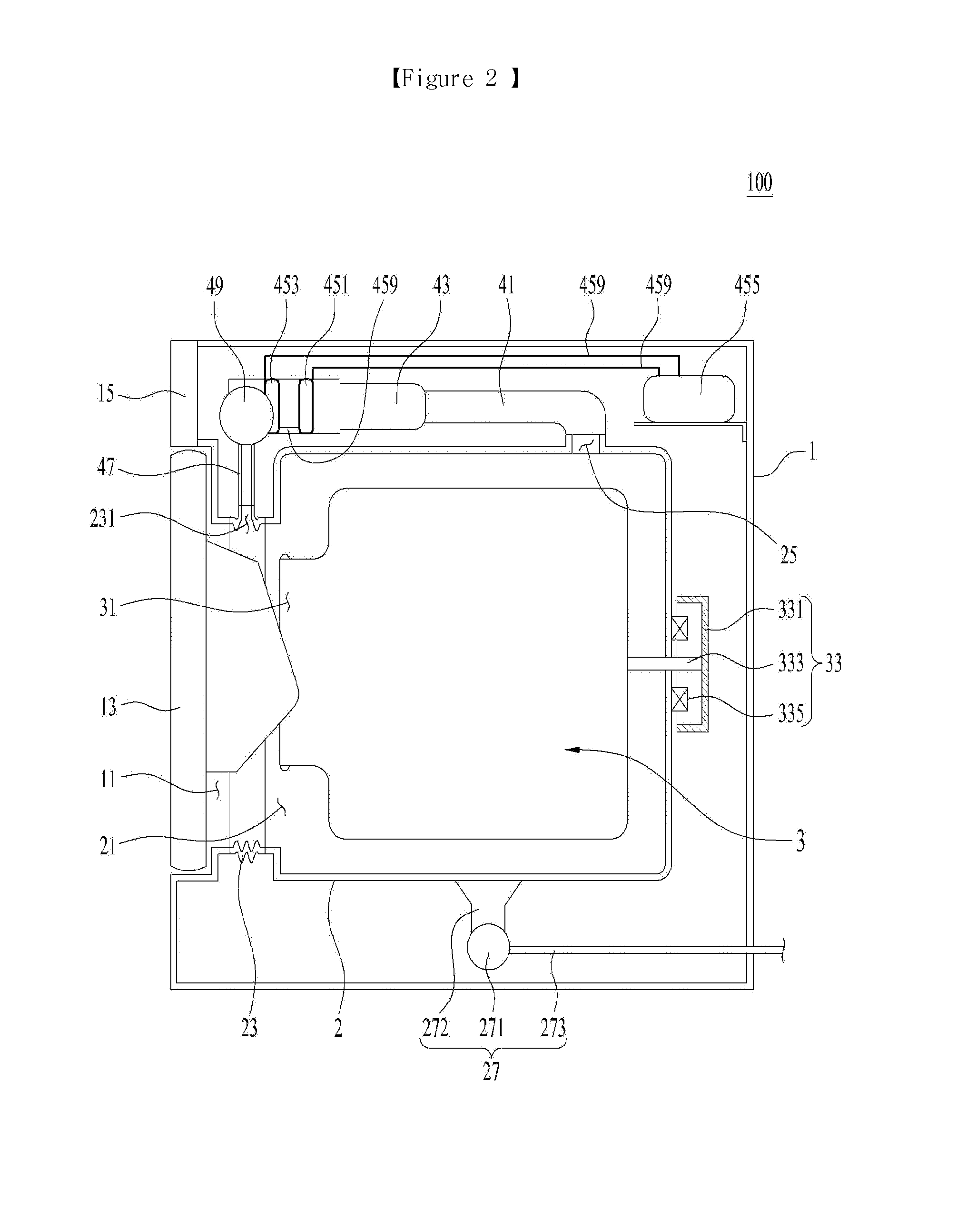
The present invention provides a laundry treatment apparatus that can accurately determine when laundry is dry based on the amount of water evaporated during the drying process. This is done by preventing impurities in the air from accumulating on a temperature sensor. The apparatus also allows for efficient heat exchange by allowing air to pass through the entire heat exchanger, resulting in high efficiency. Additionally, the apparatus ensures automated cleaning of the filter unit that filters air prior to supplying it to the heat exchanger.
Problems solved by technology
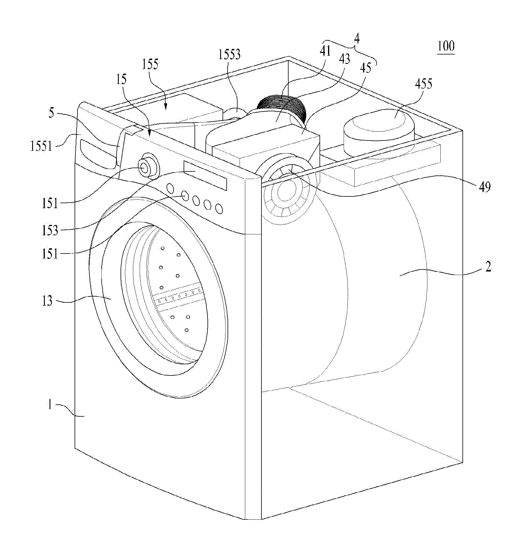
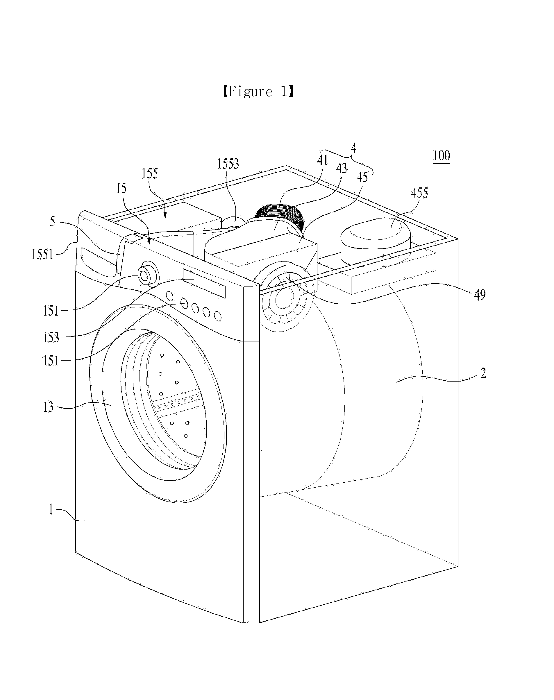
However, the above-described conventional laundry treatment apparatus, in which the blower is located in front of the heat exchanger, has a disadvantage in that air discharged from the laundry accommodation unit passes through only a portion of the heat exchanger.
Due to this disadvantage (i.e. low heat exchange efficiency), the conventional laundry treatment apparatus problematically needs to supply unnecessarily excessive amount of energy to the heat exchanger.
The above-described dryness determination method, however, has difficulty in accurately determining dryness of laundry because a temperature sensor cannot accurately measure the temperature of air discharged from the laundry accommodation unit if impurities (e.g., lint) contained in the air discharged from the laundry accommodation unit are accumulated on the temperature sensor.
Method used
View moreImage
Smart ImageViewing Examples

Examples
Embodiment Construction
[0151]As described above, a related description has sufficiently been discussed in the above “Best Mode” for implementation of the present invention.
INDUSTRIAL APPLICABILITY
[0152]As described above, the present invention may be wholly or partially applied to a laundry treatment apparatus.
Login to View More PUM
 Abstract
The present invention relates to a garment processing apparatus comprising: a hot-air supply unit having a circulation flow path for directing the air drawn out from the interior of a garment receiving unit into the interior of the garment receiving unit, a heat exchange unit provided to the circulation flow path, for condensing and heating the air introduced into the circulation flow path, and a blower for circulating the air in the interior of the garment receiving unit through the circulation flow path; and a dryness detection unit having a flow rate detection means for measuring the amount of condensate water formed in the heat exchange unit, and a control section for determining the amount of moisture contained in the laundry on the basis of the flow rate data provided by the flow rate detection means.
Description
TECHNICAL FIELD[0001]The present invention relates to a garment processing apparatus.BACKGROUND ART[0002]Garment processing apparatuses (or Laundry treatment apparatuses) are home appliances capable of washing and / or drying laundry, and include a washing machine, a drying machine, and a combined drying and washing machine.[0003]A laundry treatment apparatus capable of drying laundry is adapted to supply high temperature air (hot air), and may be divided into an exhaust type laundry treatment apparatus and a circulation type (condensation type) laundry treatment apparatus based on an air flow method.[0004]A circulation type laundry treatment apparatus, which circulates interior air of a laundry accommodation unit in which laundry is stored, is configured to implement removal of moisture (dehumidification) of air discharged from the laundry accommodation unit and to heat and resupply the air into the laundry accommodation unit.[0005]An exhaust type laundry treatment apparatus is confi...
Claims
Login to View More Application Information
Patent Timeline
 Patent Type & AuthorityApplications(United States)
IPC IPC(8): D06F58/28
CPCD06F58/28D06F2058/287D06F2058/2816D06F58/206D06F58/24D06F34/18D06F58/38D06F2103/08D06F2103/58D06F2105/26D06F2105/30D06F2103/50
InventorKO, CHEOLSOOKIM, WOORE
OwnerLG ELECTRONICS INC