Thin film coating on mechanical face seals

Inactive Publication Date: 2015-12-03
CATERPILLAR INC
View PDF3 Cites 16 Cited by
  • Summary
  • Abstract
  • Description
  • Claims
  • Application Information

AI Technical Summary

Problems solved by technology

Many applications inherently subject machine, components to extreme conditions, accelerating component wear and failure.
In earth boring, the cone is subjected to high load pressures resulting from the forces exerted on the shaft, from transient shocks that occur when crushing earthen formations, and from sliding the bit along sidewalls of the borehole.
These high pressure loads may cause the seal assembly to fail.
Furthermore, the high speeds at which the cone is requi

Method used


Image

  • Thin film coating on mechanical face seals
  • Thin film coating on mechanical face seals
  • Thin film coating on mechanical face seals

Examples


Embodiment Construction

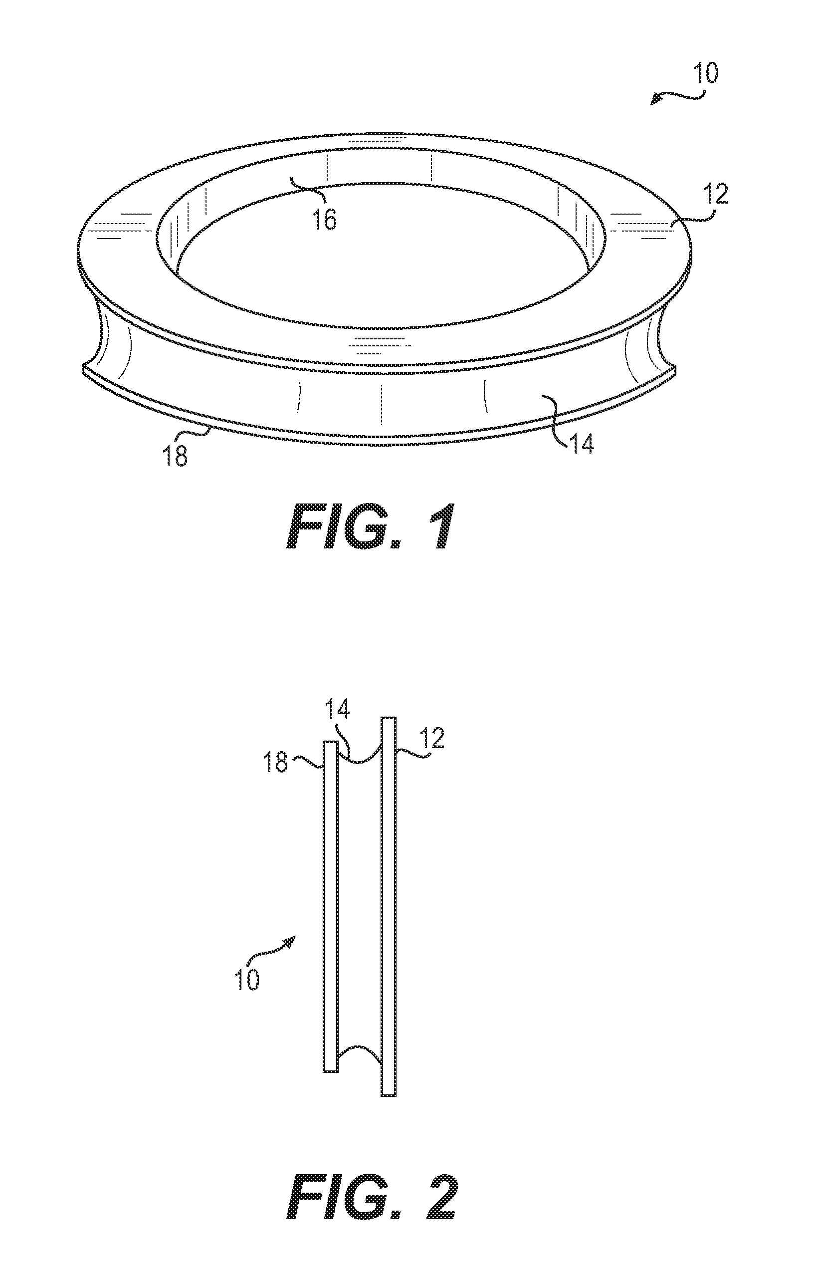
[0016]FIG. 1 illustrates a mechanical face seal 10, according to an exemplary embodiment. A side view illustration of seal 10 is shown in FIG. 2.

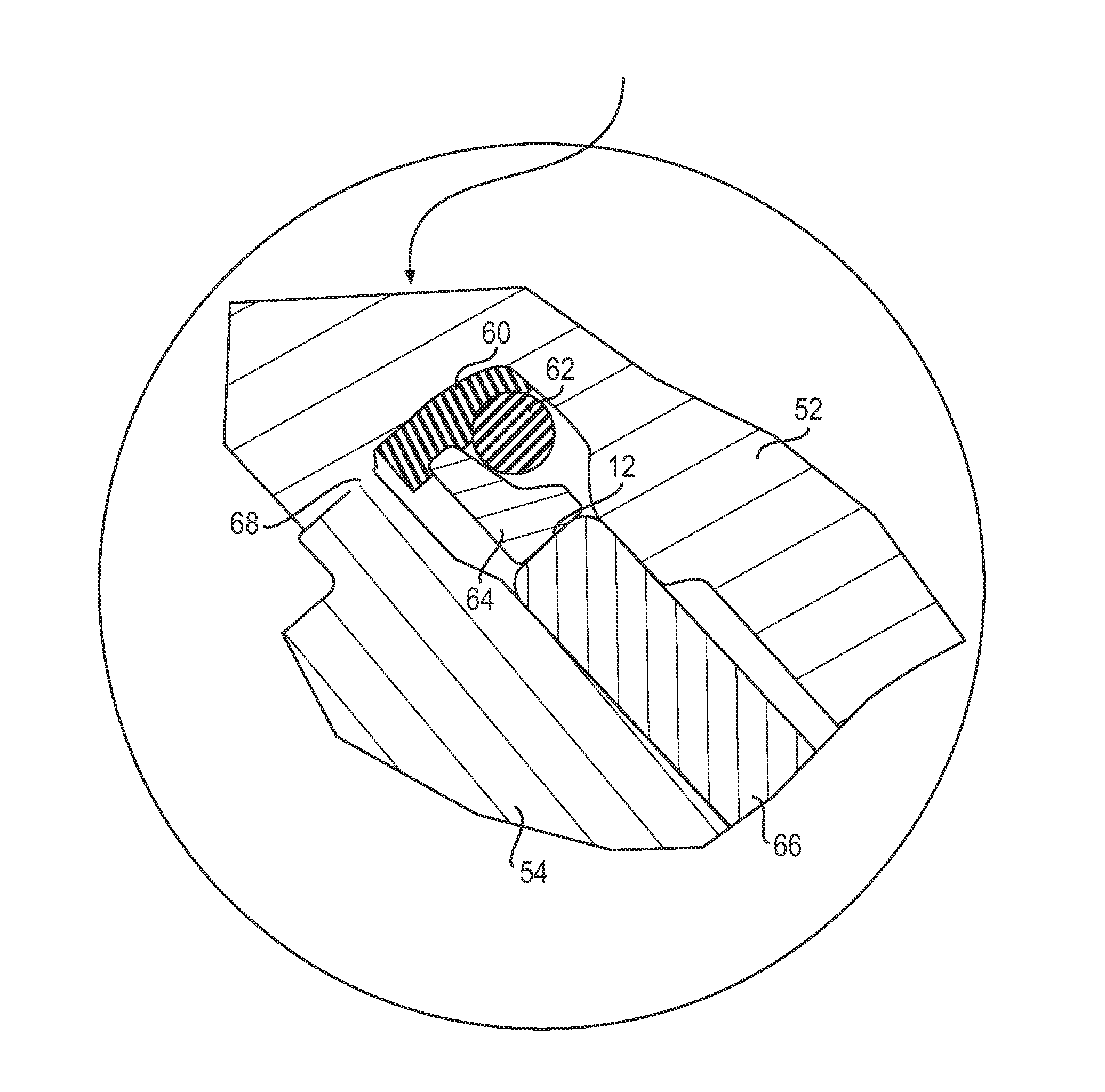
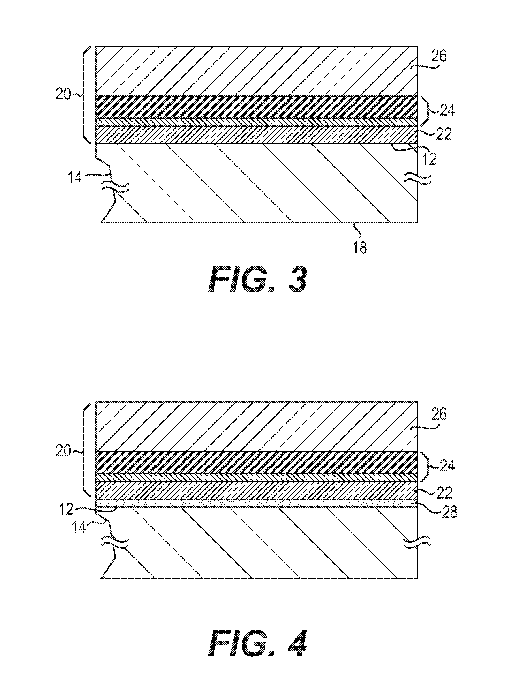
[0017]Seal 10 may include a first surface 12 disposed in a plane generally parallel to a second surface 18. Seal 10 may further include an inner surface 16 and an outer surface 14. Surface 14 may include a groove having a predetermined depth and a predetermined sidewall profile. For example, the groove may include a bottom fiat portion and curved sidewalls.

[0018]Seal 10 may be made hardened or tempered steel, or other materials suitable for fabricating mechanical face seals. By way of example, such materials may be iron, nickel, cobalt and alloys thereof, such as martensitic stainless steel or stainless steel. Further, seal 10 may be made of a ceramic material, which may provide protection from corrosion. Furthermore, while FIG. 1 illustrates surface 12 as a substantially flat surface, in other embodiments surface 12 may include a first are...


PUM

PropertyMeasurementUnit
Thicknessaaaaaaaaaa
Percent by atomaaaaaaaaaa
Thicknessaaaaaaaaaa

Abstract

A seal is disclosed. The seal has a first surface and a second surface disposed in a plane generally parallel to the first surface. At least one of the first surface and the second surface is at least partially coated with a film that includes an adhesion layer, a transition layer, and an amorphous diamond-like (a-DLC) layer.

Description

TECHNICAL FIELD[0001]The present disclosure generally relates to mechanical face seals, and more particularly, to mechanical face seals coated with thin films.BACKGROUND[0002]Many applications inherently subject machine, components to extreme conditions, accelerating component wear and failure. One such application, for example, is earth boring. In earth boring, at least one rolling cone cutter is used to drill a borehole. The rolling cone cutter mounts rotatably to a shaft that is progressively lowered in the borehole as earthen formation is pulverized.[0003]The cone's rotation with respect to the shaft is achieved using a seal assembly. Earth-boring bits may include at least one rigid seal ring disposed in a groove at the base of the shaft. This rigid seal ring has a surface that mates with a surface of a bearing sleeve located on the cone. The bearing sleeve and the rigid seal ring form a seal assembly, and they rotate relative to each other. Since the mating surfaces are metalli...

Claims


Application Information

Patent Timeline
IPC IPC(8): F16J15/34E21B10/25C23C28/00C23C14/06C23C14/14
CPCF16J15/3496C23C14/0611E21B10/25C23C28/343C23C14/14F16J15/344C23C28/322C23C16/0272C23C16/26C23C16/0281F16J15/3444
Inventor HAAS, CONNOR JOHNTAYLOR, STEVEN CHARLESMATHIEN, DANIEL EDWARDVERTENTEN, DANIEL PATRICK
Owner CATERPILLAR INC
Why Eureka
Try Eureka