Handle Sight

a technology for handle sighting and incorporating, which is applied in the field of handle sighting to achieve the effect of reducing the manufacturing cost of the handle sigh

Active Publication Date: 2015-12-03
NCSTAR
View PDF2 Cites 11 Cited by
  • Summary
  • Abstract
  • Description
  • Claims
  • Application Information

AI Technical Summary

Benefits of technology

[0007]Another advantage of the invention is to provide a handle sight, which can be detachably mounted on the firearm in a reversible orientation, per user's preferences.
[0008]Another advantage of the invention is to provide a handle sight, wherein the carrying handle has a sight channel for parallelly align with a barrel axis of the firearm to enable an operator to aim at a front iron sight of the firearm through the sight channel.
[0009]Another advantage of the invention is to provide a handle sight, wherein the foldable iron can be upwardly folded for aligning with the front iron sight of the firearm and can be downwardly folded flat on the mounting base.
[0010]Another advantage of the invention is to provide a handle sight, wherein the carrying handle further has an indented laser channel indentedly formed on the top platform for enabling a laser beam to alignedly pass along the laser channel.
[0011]Another advantage of the invention is to provide a handle sight, wherein the mounting base comprises an attachment platform for detachably coupling with a firearm accessory.
[0012]Another advantage of the invention is to provide a handle sight, which does not require altering the original mounting structure of the firearm, so as to minimize the manufacturing cost of the handle sight incorporating with the firearm.

Problems solved by technology

In other words, when the sight module is mounted on top of the firearm, the carrying handle will block the view of the sight module.

Method used


Image

  • Handle Sight
  • Handle Sight
  • Handle Sight

Examples


Embodiment Construction

[0028]The following description is disclosed to enable any person skilled in the art to make and use the present invention. Preferred embodiments are provided in the following description only as examples and modifications will be apparent to those skilled in the art. The general principles defined in the following description would be applied to other embodiments, alternatives, modifications, equivalents, and applications without departing from the spirit and scope of the present invention.

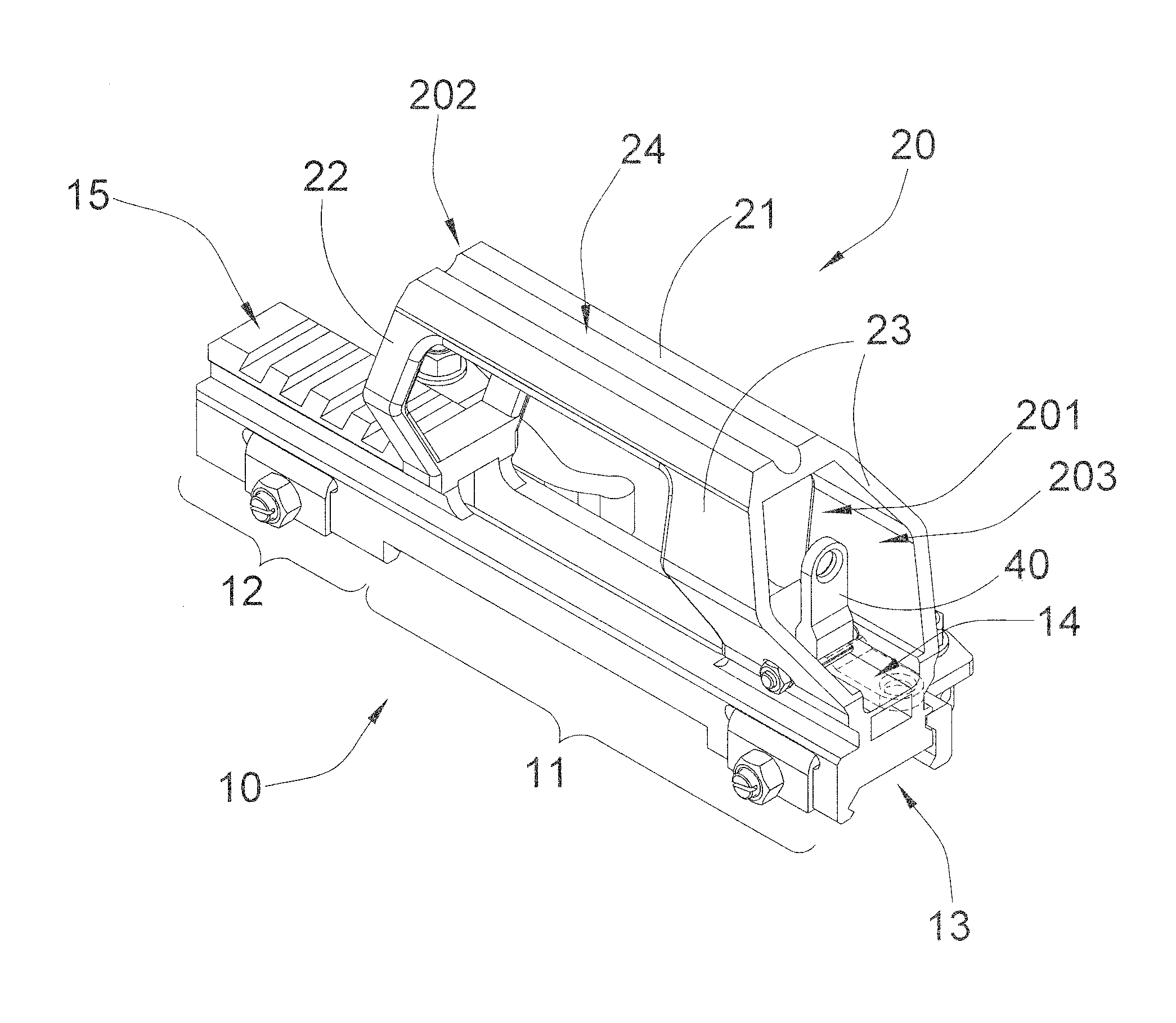
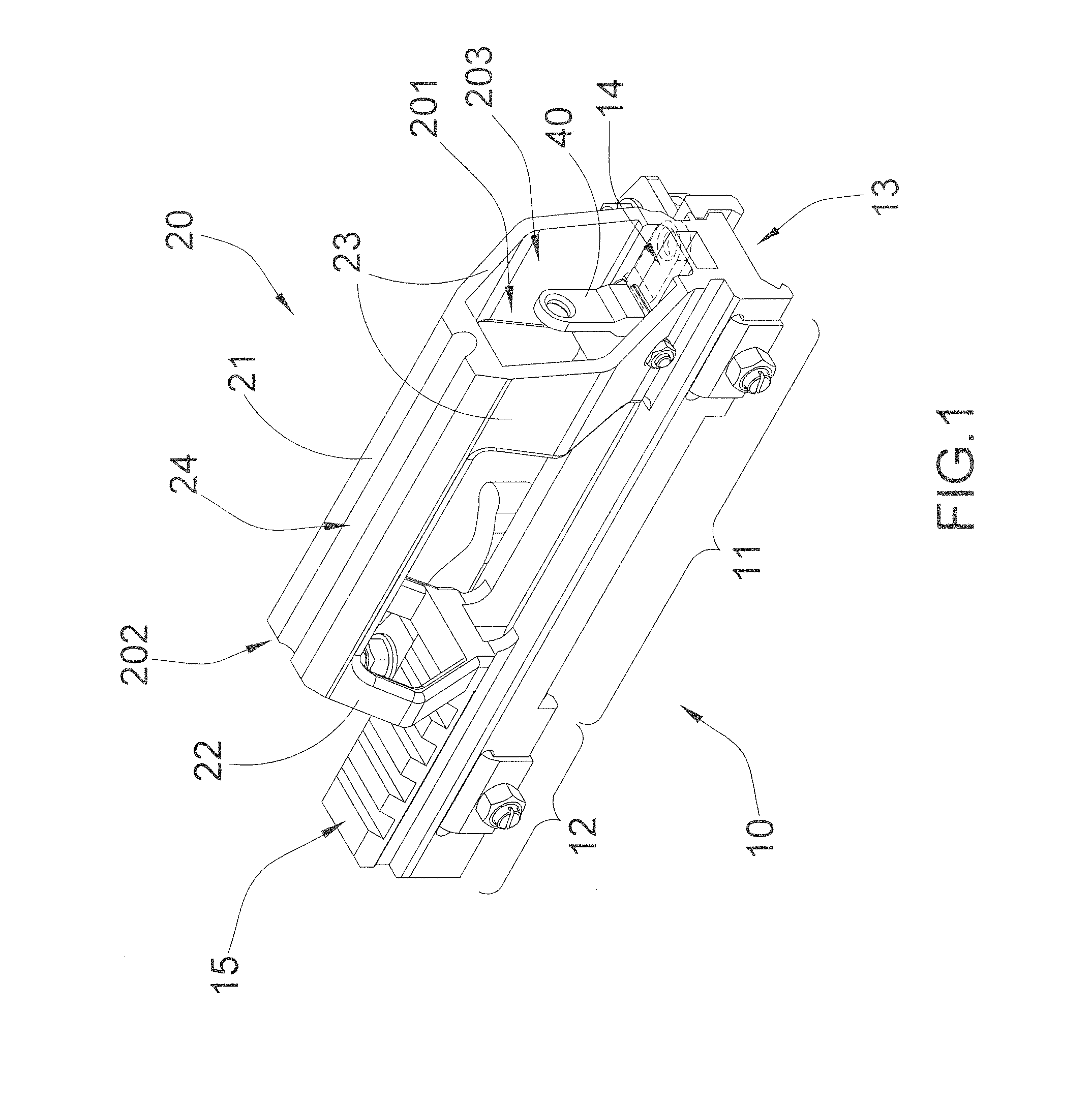
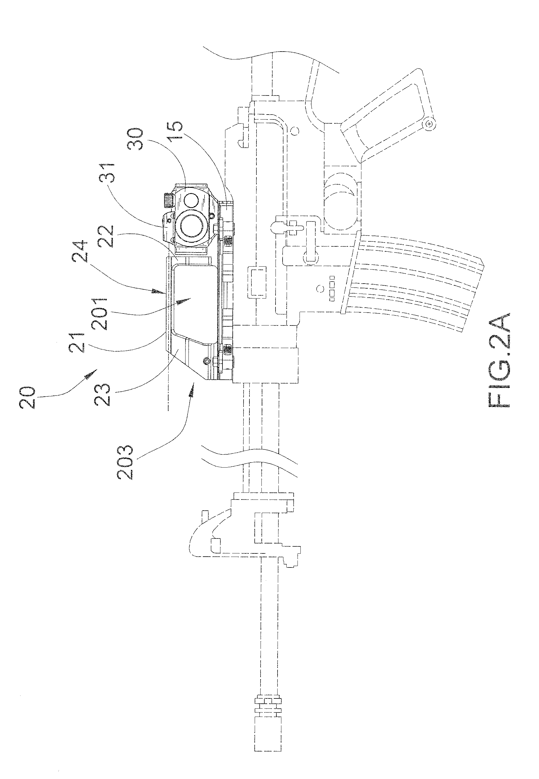
[0029]Referring to FIG. 1 of the drawings, a handle sight according to a preferred embodiment of the present invention is illustrated, wherein the handle sight, which is adapted for detachably mounting on a firearm such as a rifle, comprises a mounting base 10 and a carrying handle 20.

[0030]The mounting base 10 has an elongated shape and defining a first end portion 11 and an opposed second end portion 12, wherein the mounting base 10 is adapted for detachably mounting on the firearm in a reversi...


PUM


Abstract

A handle sight for a firearm includes a mounting base and a carrying handle. The mounting base has an elongated shape and defining a first end portion and an opposed second end portion, wherein the mounting base is adapted for detachably mounting on the firearm in a reversible orientation to locate the first end portion of the mounting base one of a forward direction and a rearward direction of the firearm. The carrying handle is upwardly extended from the first end portion of the mounting base at a top side thereof, wherein the carrying handle has a hollow structure to define a sight channel for parallelly align with a barrel axis of the firearm so as to enable an operator to aim at a front iron sight of the firearm through the sight channel.

Description

NOTICE OF COPYRIGHT[0001]A portion of the disclosure of this patent document contains material which is subject to copyright protection. The copyright owner has no objection to any reproduction by anyone of the patent disclosure, as it appears in the United States Patent and Trademark Office patent files or records, but otherwise reserves all copyright rights whatsoever.BACKGROUND OF THE PRESENT INVENTION[0002]1. Field of Invention[0003]The present invention relates to a firearm accessory, and more particular to a handle sight, which is adapted for detachably coupling at a firearm not only to provide an added-on firearm carrying handle but also to incorporate an existing sight module.[0004]2. Description of Related Arts[0005]Conventional firearm, especially for a rifle, usually does not include any carrying handle since different firearm accessories, such as a sight module, is mounted on the firearm for assisting the operator to accurately locate the target and perform the shooting....

Claims


Application Information

Patent Timeline
Patent Type & Authority Applications(United States)
IPC IPC(8): F41G1/02
CPCF41G1/02F41C33/08F41G1/08F41G1/30F41G1/387F41G11/003
Inventor CHENG, CARSONTHOMAS, RICHARD
Owner NCSTAR
Why Eureka
Try Eureka