
Systems and methods for in-trail opportunity window estimator

a technology of opportunity window and system, applied in the field of system and method of intrail opportunity window estimator, can solve the problems of complex process of identifying opportunity windows to initiate compliant itp maneuver, and the process of identifying opportunity windows for itp maneuver is further complicated

Active Publication Date: 2015-12-03
HONEYWELL INT INC
View PDF0 Cites 6 Cited by
  • Summary
  • Abstract
  • Description
  • Claims
  • Application Information

AI Technical Summary

Benefits of technology

The patent describes a system and method for identifying and displaying windows of opportunity for maneuvering an aircraft. Based on information about the aircraft's position and airspeed, the system calculates the widest time frame during which the aircraft can safely initiate a maneuver without interfering with other aircraft. This information is displayed on a screen in the form of an icon, indicating the minimum safe altitude change that can be made during the maneuver. This system helps improve safety and efficiency for aircraft maneuvers.

Problems solved by technology

However, due to aircraft traffic congestion in the various established oceanic flight routes, the crew of the aircraft must be aware of other nearby aircraft before initiating an altitude change so as to avoid a mid-air collision.
When there are multiple nearby aircraft, some of which are travelling in the same direction of the ITP aircraft and others which are travelling in opposite directions to the ITP aircraft, the process of identifying opportunity windows to initiate a compliant ITP maneuver becomes relatively complex.
The process of identifying ITP maneuver opportunity windows is further complicated when the multiple nearby aircraft are travelling at different velocities and altitudes.

Method used


Image

  • Systems and methods for in-trail opportunity window estimator
  • Systems and methods for in-trail opportunity window estimator
  • Systems and methods for in-trail opportunity window estimator

Examples


Embodiment Construction

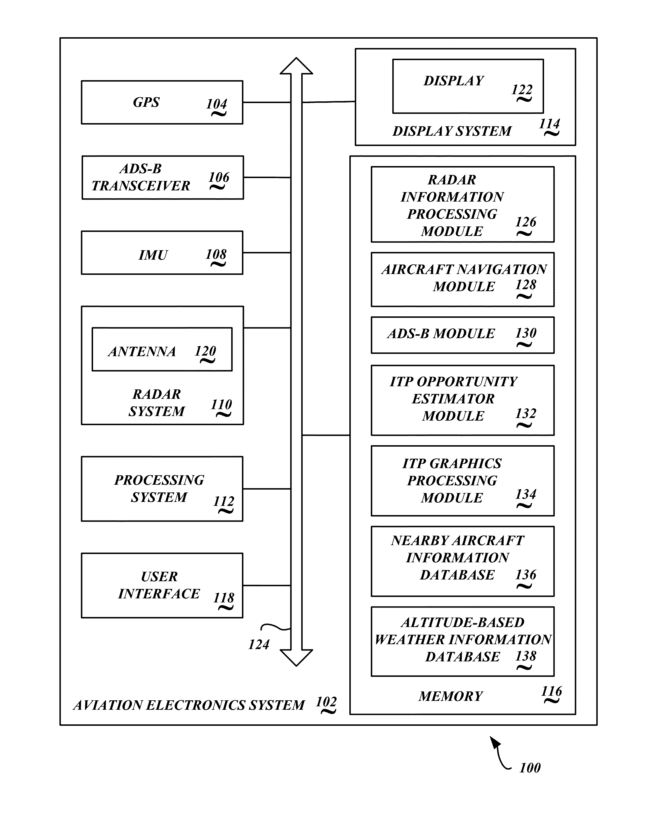
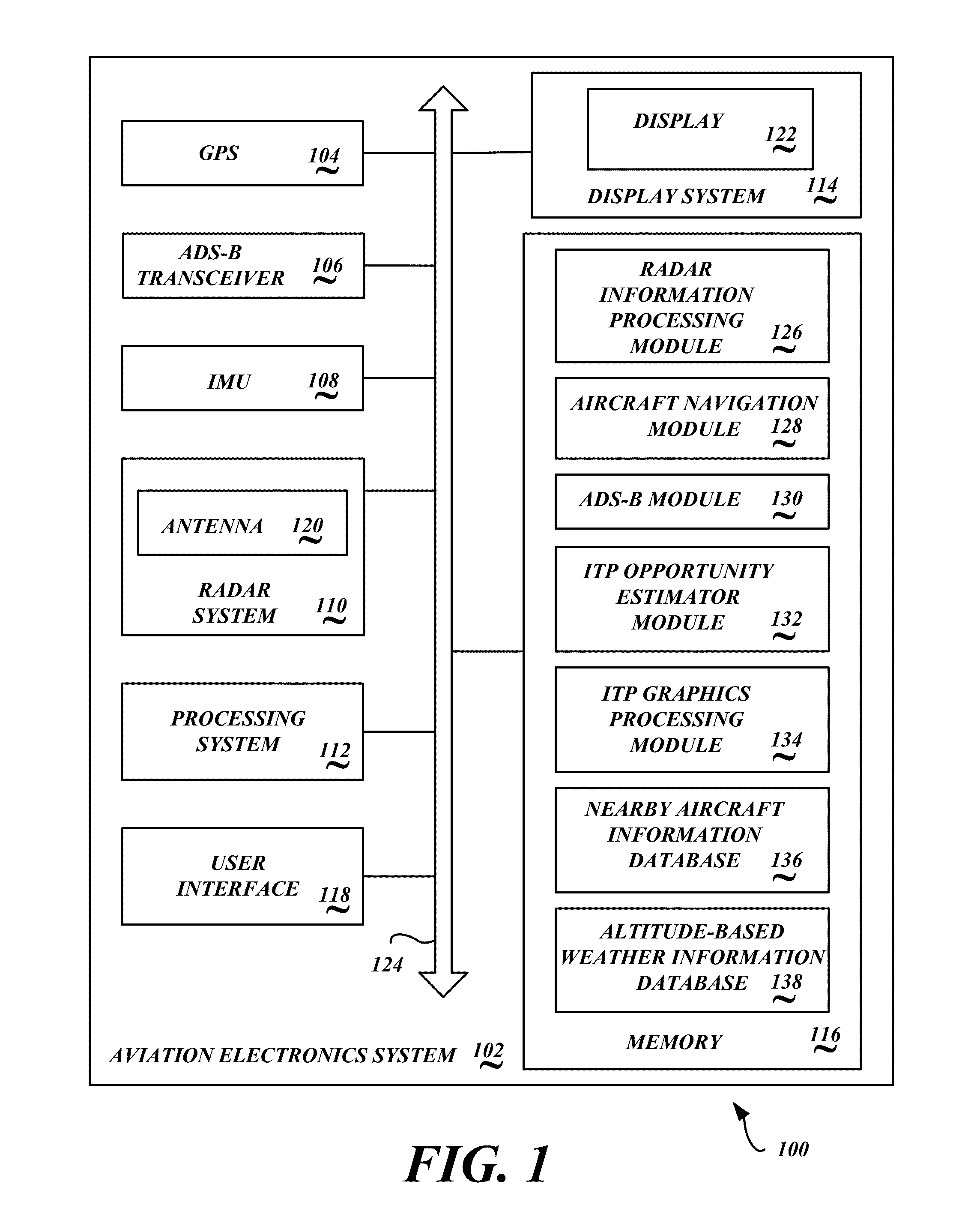
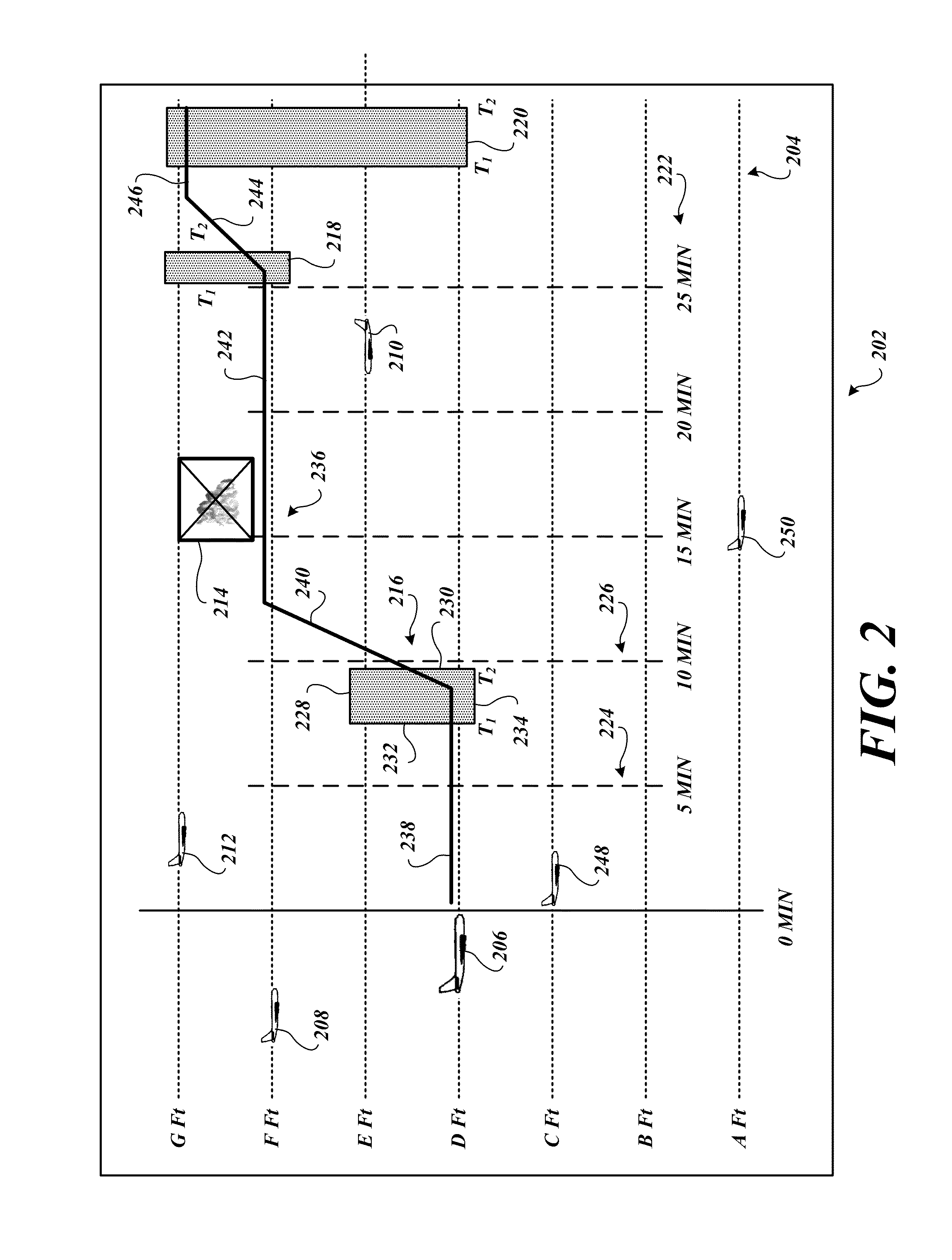
[0014]Systems and methods of identifying In-Trail procedure (ITP) maneuver opportunity windows and presenting ITP maneuver opportunity window information to the crew are disclosed. Embodiments of the ITP maneuver opportunity window estimator system 100 are operable to identify, determine, or estimate a plurality of ITP ascent maneuver opportunity windows and a plurality of ITP descent maneuver opportunity windows for an ITP aircraft in view of other nearby aircraft so that minimum safe self-separation distances are maintained between the ascending (or descending) ITP aircraft and other nearby aircraft. Further, embodiments of the ITP maneuver opportunity window estimator system 100 are operable to further consider nearby weather conditions such that identified ITP ascent maneuver opportunity windows and / or ITP descent maneuver opportunity windows do not require the ITP aircraft to travel through potentially unsafe weather conditions. Also, embodiments of the ITP maneuver opportunity...


PUM


Abstract

Systems and methods are operable to identify and indicate opportunities for an In-Trail procedure (ITP) aircraft to make an ITP altitude change. An exemplary embodiment receives information corresponding to a desired ITP altitude for the ITP aircraft and a projected window period; estimates at least one ITP maneuver opportunity window based on the estimated location of each of the plurality of other aircraft and based on a current airspeed and a current altitude of the ITP aircraft; generates a screen shot that presents an ITP maneuver opportunity window icon, wherein the ITP maneuver opportunity window icon graphically indicates the soonest time and the latest time that the ITP aircraft may initiate the ITP maneuver, and wherein the ITP maneuver opportunity window icon indicates an altitude change made by the ITP aircraft will maintain minimum safe self-separation distances from the plurality of other aircraft during the ITP maneuver.

Description

BACKGROUND OF THE INVENTION[0001]During oceanic flights, crew of an aircraft may wish to adjust the flight level of their aircraft to take advantage of favorable winds that may be found at different altitudes, thereby improving fuel efficiency and / or reducing flight times. For example, if the aircraft is travelling in the direction of the jet stream, it is desirable for the aircraft to fly within the jet stream so as to take advantage of prevailing wind speeds. Conversely, if the aircraft is heading in a direction that opposes prevailing wind speeds, it is desirable to fly at an altitude where the prevailing opposing wind speeds are absent or are minimal.[0002]However, due to aircraft traffic congestion in the various established oceanic flight routes, the crew of the aircraft must be aware of other nearby aircraft before initiating an altitude change so as to avoid a mid-air collision. That is, the crew of the aircraft must know the location, bearing, altitude, and airspeed of near...

Claims


Application Information

Patent Timeline
Patent Type & Authority Applications(United States)
IPC IPC(8): G08G5/00B60K35/00G01S13/931
CPCG01S13/931G08G1/16G08G5/0008G08G5/0021G08G5/0039
Inventor KASHI, RAJANIKANTH NAGARAJRATHBUN, ROGERGREMMERT, SCOTT RICHARDMATHEWS, DILIPKUMBLE, NAINATARA
Owner HONEYWELL INT INC
Learn More