Modular strap mount for solar panels

Active Publication Date: 2015-12-03
SOLARSTRAP TECH LLC
View PDF8 Cites 3 Cited by
  • Summary
  • Abstract
  • Description
  • Claims
  • Application Information

AI Technical Summary

Benefits of technology

[0016]An appreciation of the other aims and objectives of the present invention and a more complete and comprehensive understanding of it may

Problems solved by technology

Such systems are heavy and expensive to

Method used


Image

  • Modular strap mount for solar panels
  • Modular strap mount for solar panels
  • Modular strap mount for solar panels

Examples


Embodiment Construction

[0055]While the present invention is described herein with reference to illustrative embodiments for particular applications, it should be understood that the invention is not limited thereto. Those having ordinary skill in the art and access to the teachings provided herein will recognize additional modifications, applications, and embodiments within the scope thereof and additional fields in which the present invention would be of significant utility.

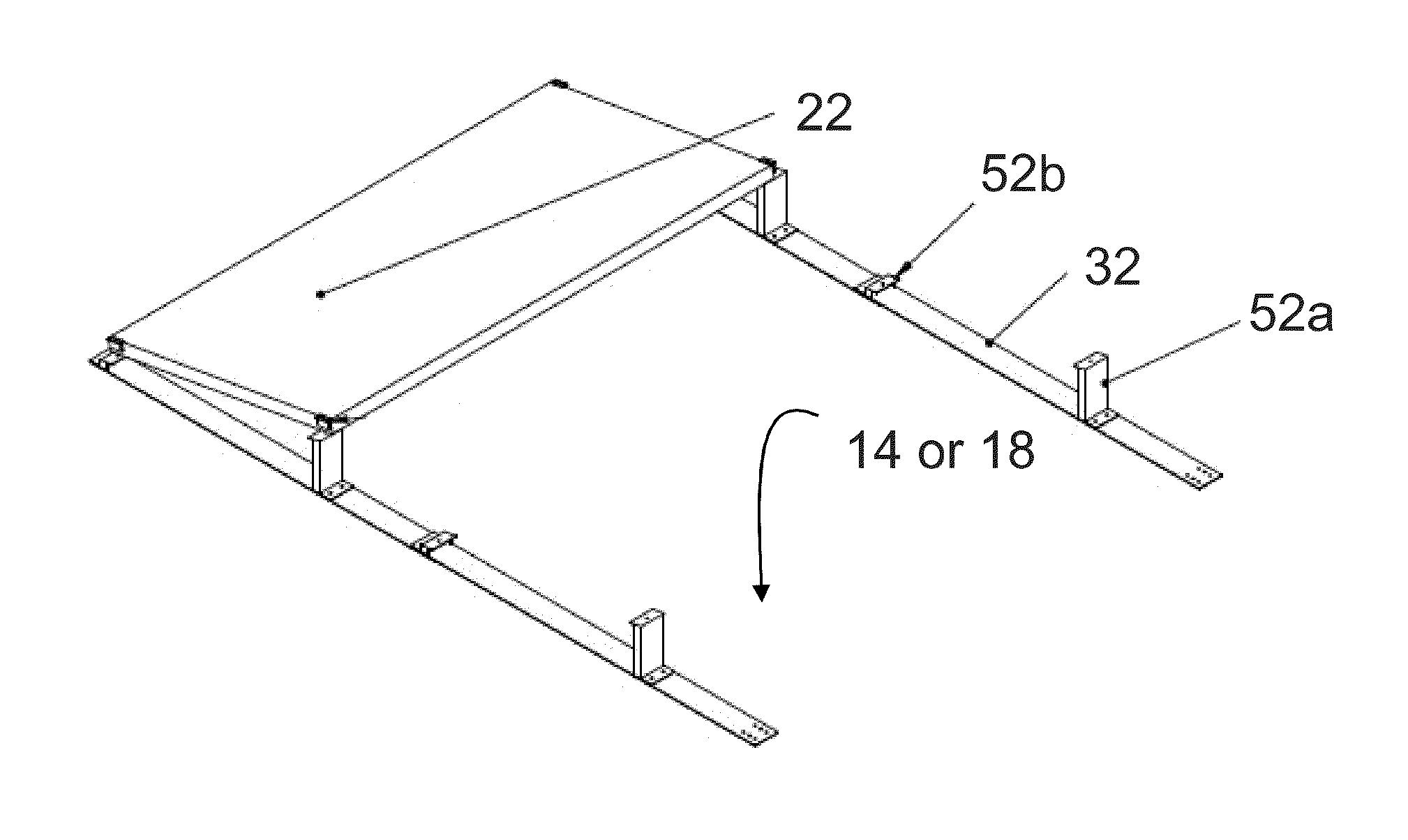
[0056]This invention 10 has two major embodiments: one 10a that is intended primarily to be attached to a flat surface 14, such as a roof or wall; and one that is intended to be attached primarily to a tilted surface 18, such as a peaked roof. However, in fact, either embodiment can be attached to a flat 14 or tilted 18 surface. As described in U.S. Pat. No. 7,814,899, solar panels 22 may be retained within a frame 24 (as shown in FIG. 7), which has a number of holes useful for mounting.

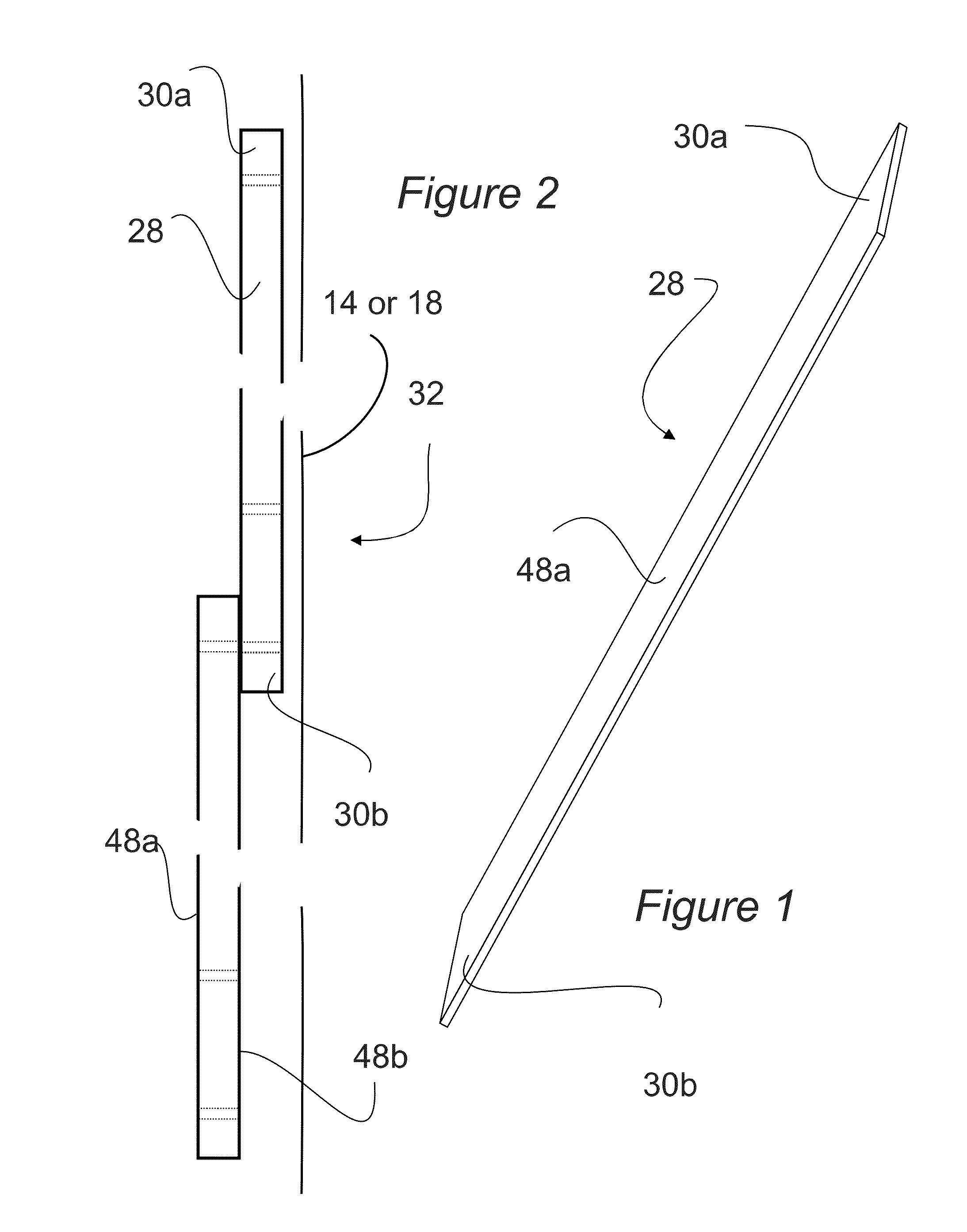
[0057]FIG. 1 illustrates the modular strap 28 of...


PUM


Abstract

A method and apparatus for mounting a solar collector panel by itself or supported within a frame, to a surface comprising: a strap assembly, a first attachment device attached to and between the panel or frame and the strap assembly; and a second attachment means for attaching the strap assembly to the surface. The strap assembly comprises a plurality of straps attached end to end. The first attachment device could be a bolt, a screw, adhesive, etc. Alternatively, there could be a support between the panel or frame and the strap assembly. The second attachment means may be: a nail, a spike, adhesive, bolting to a stud attached to the surface, welding, ballast, adhesive tape or combinations of these.

Description

CROSS REFERENCE TO RELATED APPLICATIONS[0001]This application is a Continuation of PCT Patent Application No. PCT / US2013 / 025622 filed 11 Feb. 2013, the entire specification claims and drawings of which are hereby incorporated by reference.BACKGROUND OF THE INVENTION[0002](1) Field of the Invention[0003]The present invention relates to the field of solar panels and more particularly to apparatuses and methods for mounting solar panels on surfaces, including roofs, walls and the ground.[0004](2) Description of the Related Art[0005]Solar panels can be of the photovoltaic type of the thermal type or combinations. They can be installed as is or contained within a frame. Solar panels must be mounted correctly in order to maximize power production and to prevent movement of the panels from the force of wind. The proper solar panel mounting provides stability and the proper directional and latitudinal orientation for the solar array.[0006]Different mounting systems are available depending o...

Claims


Application Information

Patent Timeline
IPC IPC(8): H02S20/22E04B1/41
CPCH02S20/22E04B2001/405E04B1/40F24S25/16F24S25/50F24S25/61Y02B10/10Y02E10/47Y02E10/50
Inventor PORT, JONATHAN
Owner SOLARSTRAP TECH LLC
Why Eureka
Try Eureka