
Predicting the potential for severe weather

a weather and severe technology, applied in the field of forecasting the potential for severe weather, can solve problems such as lightening activity, and achieve the effects of reducing the risk of dangerous weather activity, and reducing the risk of lightening activity

Active Publication Date: 2014-09-16
EARTH NETWORKS
View PDF73 Cites 3 Cited by
  • Summary
  • Abstract
  • Description
  • Claims
  • Application Information

AI Technical Summary

Benefits of technology

Enables timely and accurate automated severe weather alerts, increasing safety by providing early warnings to affected areas through precise detection and prediction of severe weather phenomena.

Problems solved by technology

An increase in lightning activity often precedes even more severe weather phenomena, such as severe storms, tornadoes, hail, damaging downburst winds and potentially deadly cloud-to-ground lightning strikes.

Method used


Image

  • Predicting the potential for severe weather
  • Predicting the potential for severe weather
  • Predicting the potential for severe weather

Examples


Embodiment Construction

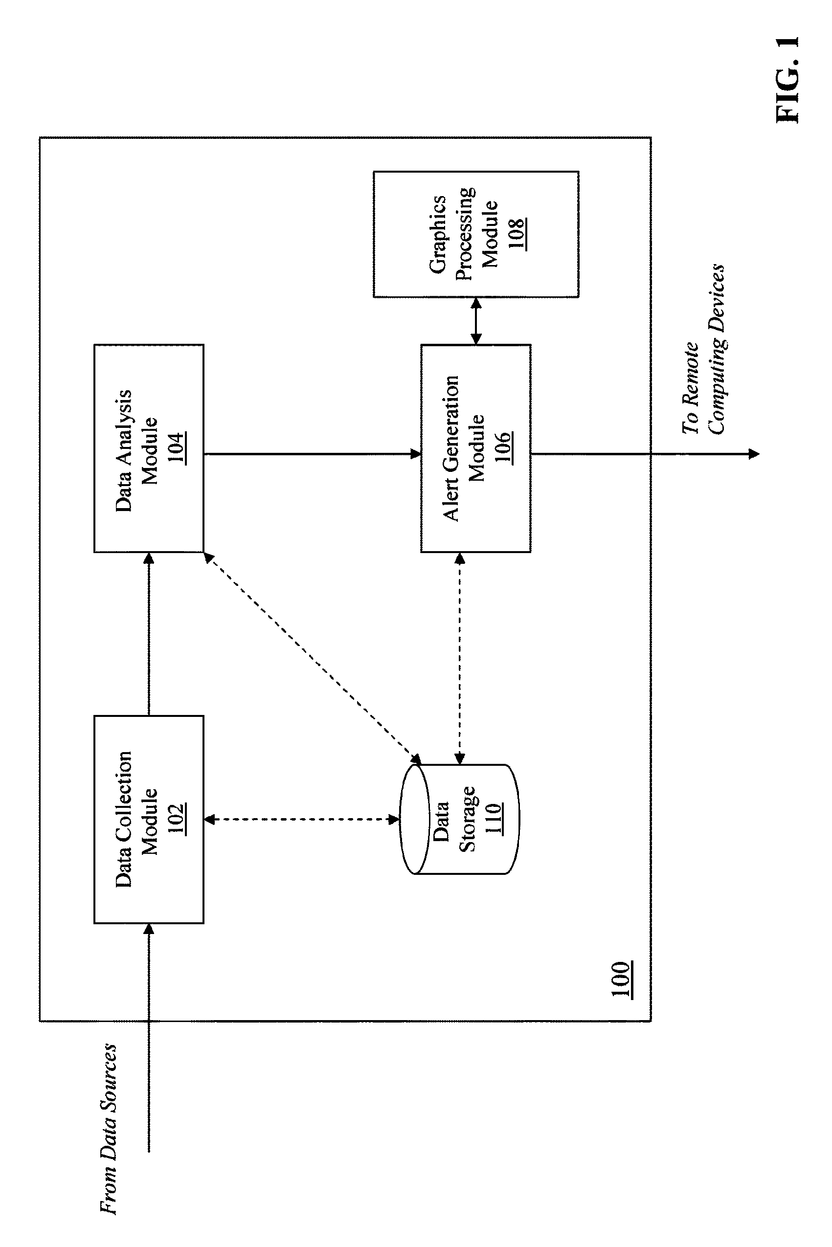
[0023]FIG. 1 is a block diagram of a system 100 for predicting the potential for severe weather. The system 100 includes a data collection module 102, a data analysis module 104, an alert generation module 106, a graphics processing module 108, and a data storage module 110. In some embodiments, the components (e.g., 100, 102, 104, 106, 108 and 110) of the system 100 reside at the same physical location or may be dispersed to different physical locations. In some embodiments, the components of the system 100 are located on the same physical device (e.g., a server computing device), or are distributed on different physical devices. The components of the system 100 communicate, for example, via a communications network (e.g., WAN, LAN, VLAN).

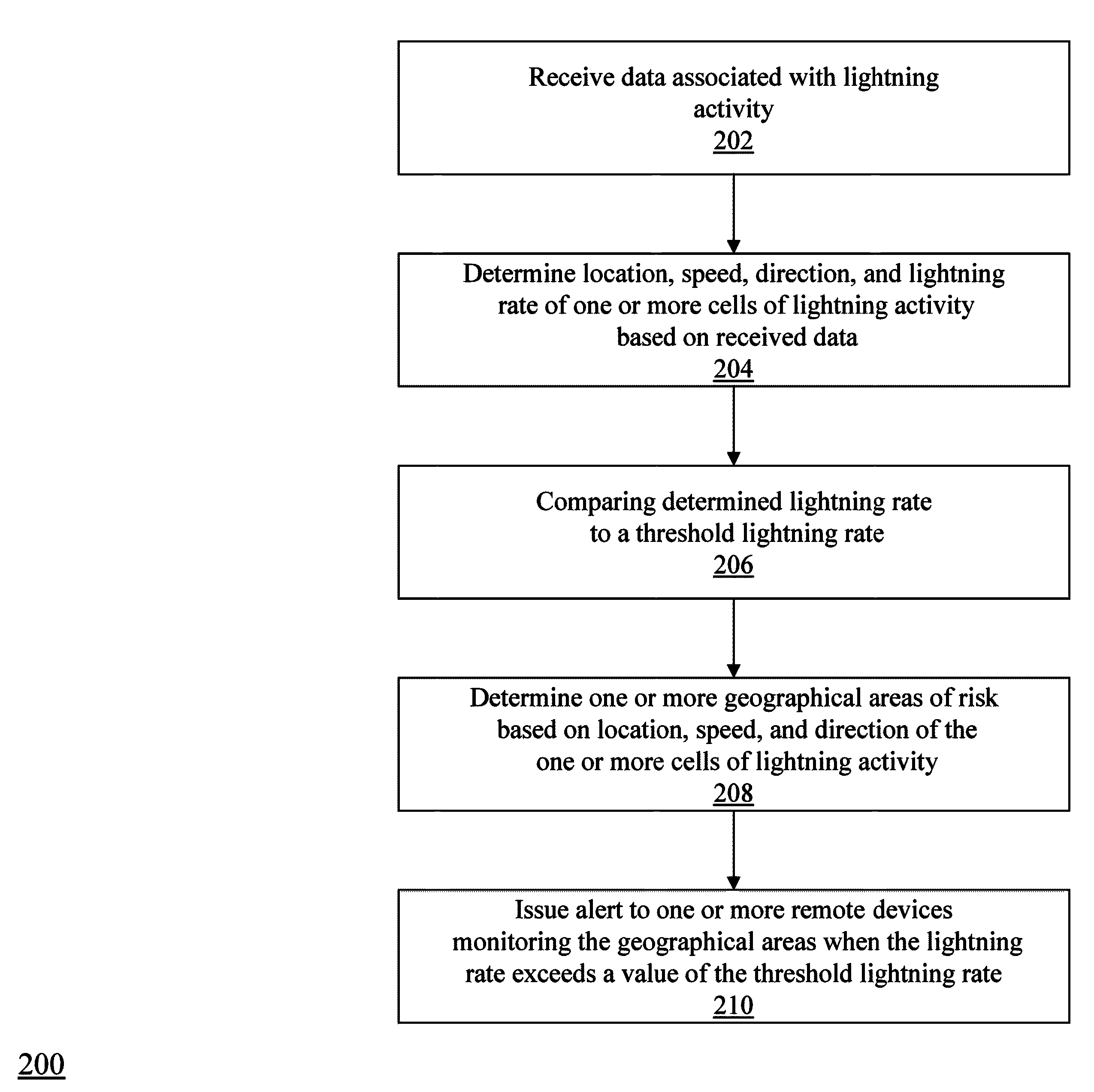
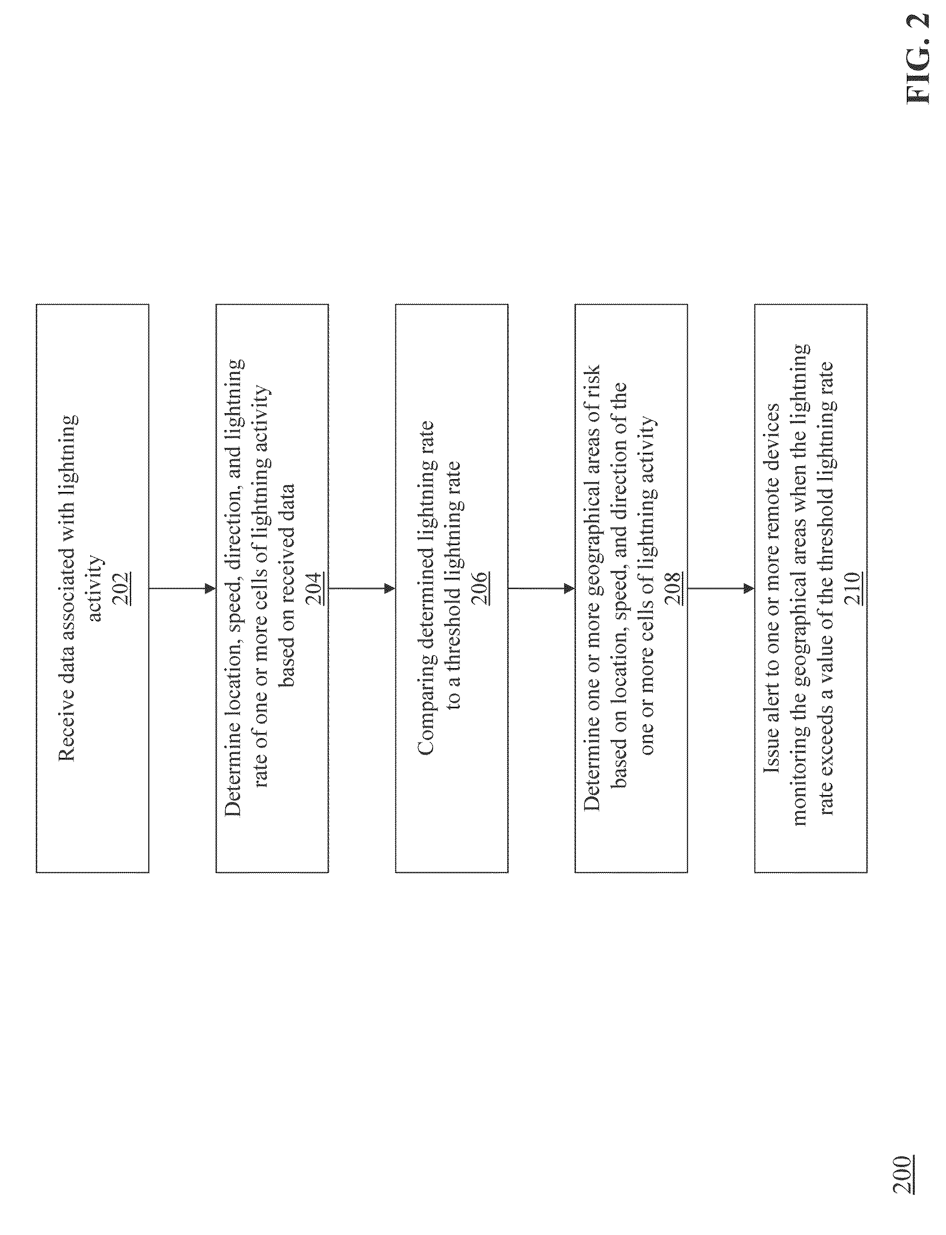
[0024]FIG. 2 is a flow diagram of a method 200 for predicting the potential for severe weather using the system 100. The data collection module 102 receives (202) data associated with lightning activity. The data analysis module 104 determines (20...


PUM


Abstract

Methods and apparatuses, including computer program products, are described for predicting the potential for severe weather. Data associated with lightning activity is received by a computing device. A location, a movement speed, a movement direction, and a lightning rate of one or more cells of lightning activity are determined by the computing device based on the received data. The lightning rate is compared, by the computing device, to a threshold lightning rate. One or more geographical areas at risk are determined by the computing device based on the location, the movement speed and the movement direction of the one or more cells of lightning activity. An alert is issued by the computing device to one or more remote devices monitoring the geographical areas when the lightning exceeds a value of the threshold lightning rate.

Description

FIELD OF THE INVENTION[0001]The subject matter of this application relates generally to methods and apparatuses, including computer program products, for predicting the potential for severe weather.BACKGROUND OF THE INVENTION[0002]Lightning includes electrical discharges within a cloud, intracloud (IC) discharges, and cloud to ground (CG) discharges. Lightning occurs when electrical fields within a cloud intensify as particles of opposite polarity collect at differing regions within the cloud. Lightning begins with an initial electrical breakdown (i.e., a pulse) followed by leader channels from which a series of channel branches grow within a cloud forming a comprehensive branch channel structure. For IC lightning, the channel structure remains within the cloud. A CG discharge occurs when one or more branches extend from a cloud to the ground.[0003]An increase in lightning activity often precedes even more severe weather phenomena, such as severe storms, tornadoes, hail, damaging do...

Claims


Application Information

Patent Timeline
Patent Type & Authority Patents(United States)
IPC IPC(8): G01W1/00G01W1/10G01W1/16
CPCG01W1/16G01W1/10Y02A50/00G01W1/02G01W2203/00G08B21/10G08G1/0967
Inventor MARSHALL, ROBERT S.SLOOP, CHRISTOPHER DALEBEROUKHIM, BENJAMIN E.LIU, CHONGLINHECKMAN, STANHOEKZEMA, MARK A.
Owner EARTH NETWORKS
Learn More