Method for projecting virtual data and device enabling this projection

a technology of which is applied in the field of projecting virtual data and projection device, can solve the problem that the positioning of markers is often a source of errors

Active Publication Date: 2015-12-03
AIRBUS
View PDF14 Cites 14 Cited by
  • Summary
  • Abstract
  • Description
  • Claims
  • Application Information

AI Technical Summary

Benefits of technology

[0013]The present invention aims to alleviate all or some of the drawbacks of the prior art by providing a devi

Problems solved by technology

This step of positioning markers is often a source o

Method used


Image

  • Method for projecting virtual data and device enabling this projection
  • Method for projecting virtual data and device enabling this projection
  • Method for projecting virtual data and device enabling this projection

Examples


Embodiment Construction

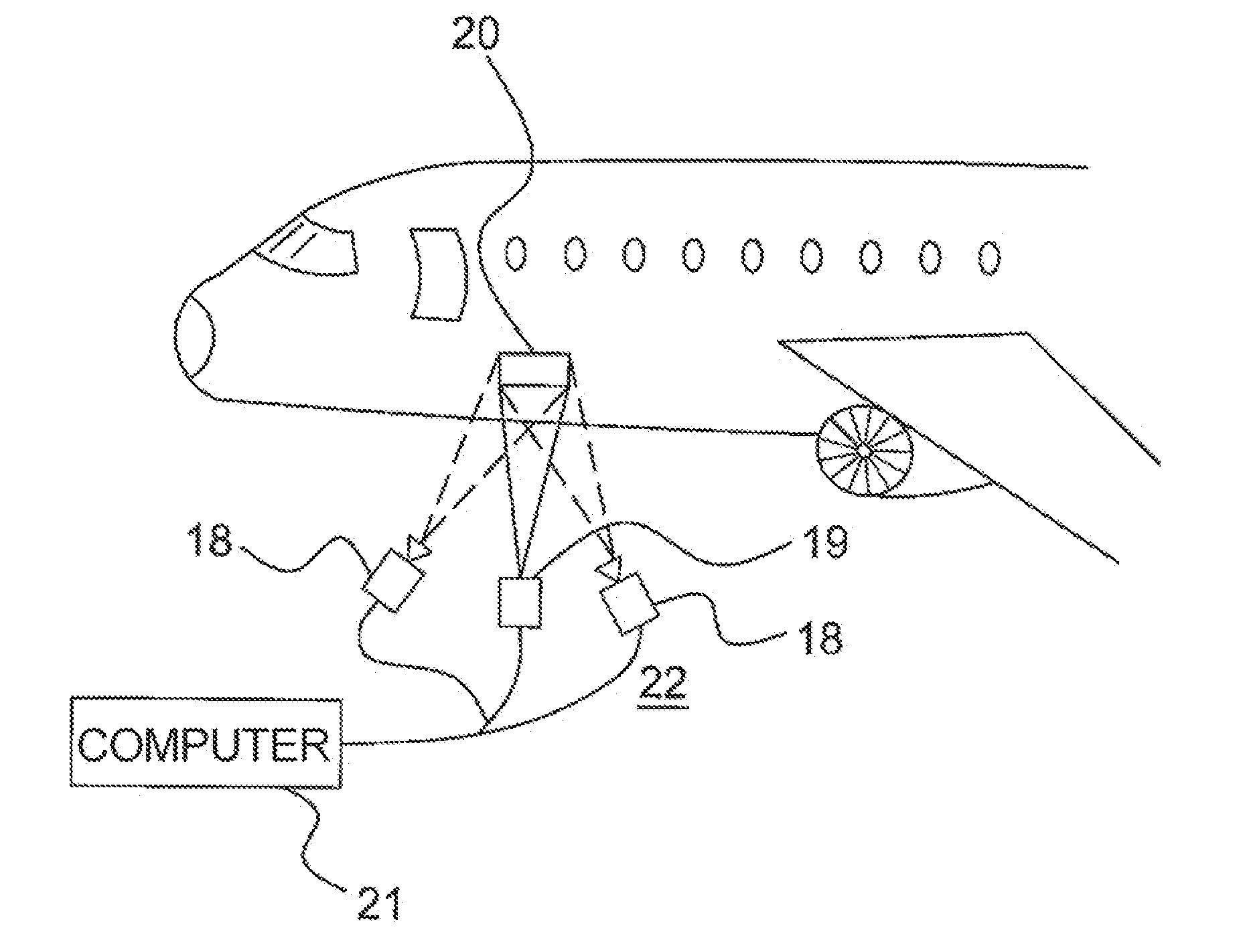
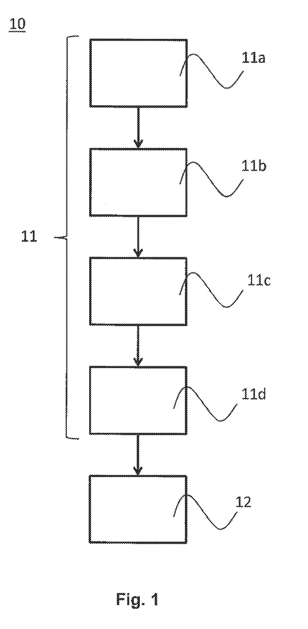
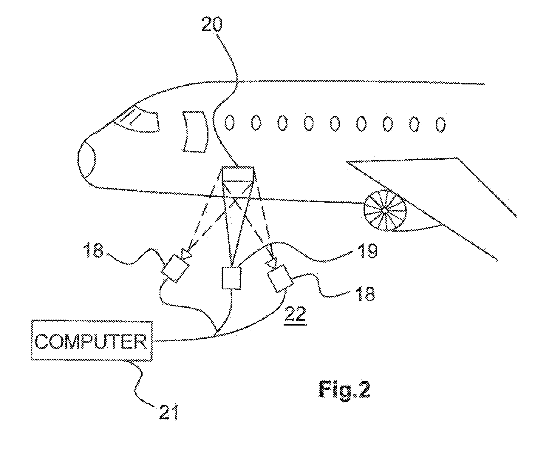
[0043]FIG. 1 is a flowchart showing the method 10 according to one embodiment of the invention. In a first step 11, a calibration is carried out. This step 11 comprises a substep 11a of projecting, using a video projector 19, calibration patterns onto a surface of interest 20 that may be seen in FIG. 2. In a subsequent substep 11 b, at least two image-capturing devices will acquire characteristic data by analysing the calibration patterns projected onto the surface of interest 20. Specifically, the image-capturing devices 18 capture the rendering of the pattern on the surface of interest 20 and said rendering is then analysed by computer 21 in order to be expressed as a set of characteristic data forming a three-dimensional structure. In a subsequent substep 11c, the characteristic data are compared with data issued from a digital design model thus allowing, by way of a vision algorithm, a set of correspondences between the image-capturing devices 18 and the video projector 19 to be...


PUM


Abstract

A method for projecting information issued from a digital design model. Calibration is performed by acquiring characteristic data originating from a surface of interest and comparing the characteristic data with virtual data issued from the digital design model. A spatial position of a projecting device is determined. The projecting device comprises a video projector and at least two separate image-capturing devices. Depending on the spatial position, information issued from the digital design model is projected by the video projector onto the surface of interest.

Description

FIELD OF THE INVENTION[0001]The present invention relates to a method for projecting, onto a surface of interest, virtual data originating from a digital design model produced by an engineering and design department.[0002]It is applicable to many fields, especially the aeronautical, construction, shipbuilding or even aerospace fields.[0003]The present invention is more particularly applicable to large objects such as aircraft, helicopters or even satellites, during stages of construction, assembly or even maintenance thereof.PRIOR ART[0004]Knowledge of the state of an actual object during manufacture or even during operation is often partial. A manufacturer generally has at their disposal collections of measurements in folders of files (for example spreadsheets, photos or files of measurements) or in databases. It is then difficult, and in particular for large objects, not only to locate the data issued from actual measurements associated with a particular zone and to ascertain wher...

Claims


Application Information

Patent Timeline
IPC IPC(8): H04N9/31
CPCH04N9/3185H04N9/3141H04N9/3191B25H7/00G01S5/16G03B21/00G09F19/18H04N9/3194G03B17/54G01N21/8803G06V20/653G01N21/956
Inventor CHEVASSUS, NICOLASMARRAUD, DENISTARAULT, ANTOINEPERROTTON, XAVIER
Owner AIRBUS
Why Eureka
Try Eureka