Substrate cleaning apparatus

Active Publication Date: 2015-12-10
EBARA CORP
View PDF6 Cites 3 Cited by
  • Summary
  • Abstract
  • Description
  • Claims
  • Application Information

AI Technical Summary

Benefits of technology

The patent text describes a substrate cleaning apparatus that prevents a substrate from becoming warped when cleaned using a swing cleaning member. The apparatus includes a plurality of outer circumference supporting members that support the outer circumference of the substrate and an elongated supporting member that passes through the center portion of the substrate to support the rear surface of the rotating substrate. The technical effect of this invention is to prevent substrate warping during cleaning, which can lead to variations in cleaning characteristics and lower throughput.

Problems solved by technology

Accordingly, when a substrate front surface is not sufficiently cleaned, such as when a substrate front surface is complex and difficult to clean, leakage and / or poor adhesiveness may occur according to the effect of the residue or the like, causing reliability to lower.
This problem with the warped shape caused from the pressing force by the cleaning member may occur also when the substrate is placed vertically or obliquely, not limited to when the substrate is placed flat in the horizontal direction.
For example, if a substrate is placed flat in the horizontal direction, a scrubbing solution is discharged by centrifugal force generated by rotating the substrate, but if the central portion of the substrate becomes concave, discharging performance of the scrubbing solution lowers.
The problem that the discharging performance of the scrubbing solution lowers has particularly a large effect on rinsing after cleaning by using a medical solution, accordingly, a margin in an integrated cleaning process may be reduced, a throughput may be lowered due to a long time processing and a high cost may be incurred because of consumption material.
That is, once a substrate becomes warped, a pressing force by a cleaning member lowers in the central portion of the substrate, and the cleaning characteristic may deteriorate in the central portion of the substrate (where a whirl speed is low).
Then, if the pressing force by the cleaning member is simply strengthened, a corner of the cleaning member comes into contact with the outer circumferential portion of the substrate (where a whirl speed is high) and back contamination may increase.

Method used


Image

  • Substrate cleaning apparatus
  • Substrate cleaning apparatus
  • Substrate cleaning apparatus

Examples


Embodiment Construction

[0030]Now, a substrate cleaning apparatus of an embodiment will be described. Note that an embodiment to be described below shows one example where this technology is implemented, and this technology should not be limited to a specific configuration to be described below. When this technology is implemented, a specific configuration may be appropriately adopted depending on an embodiment.

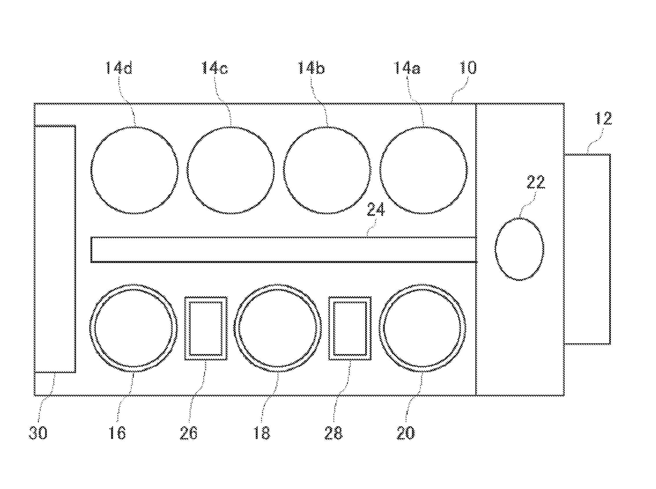
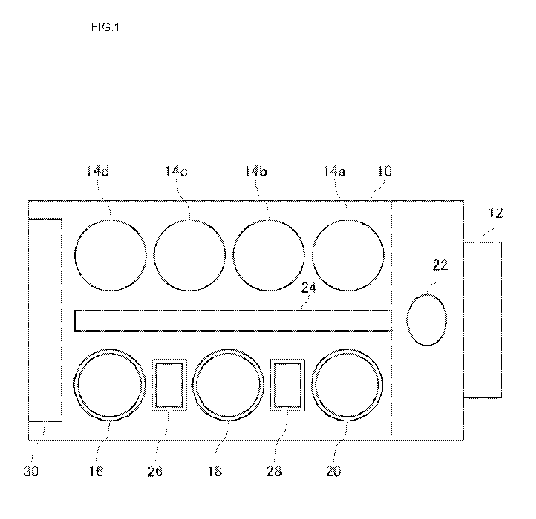
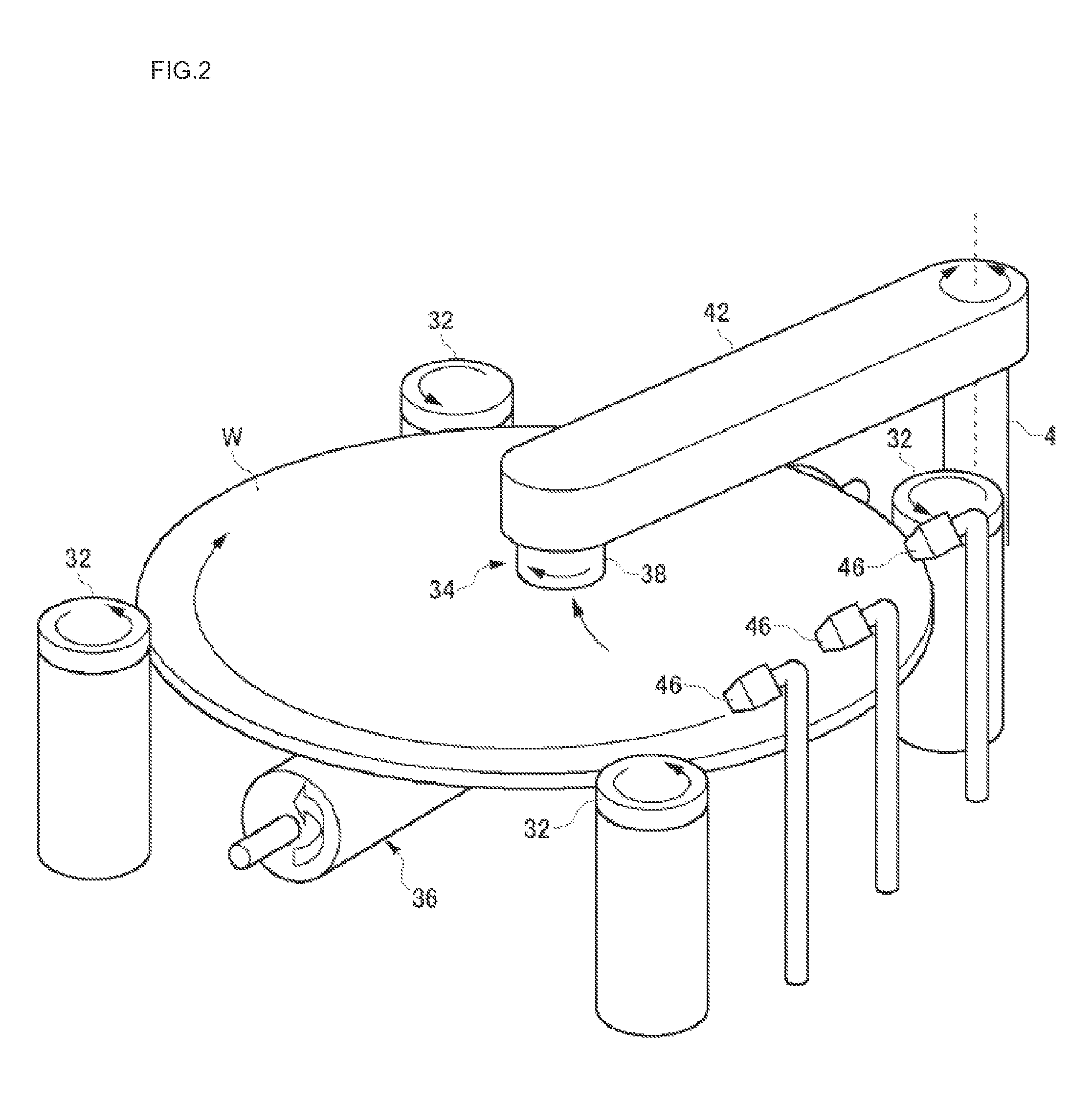
[0031]A substrate cleaning apparatus of one embodiment includes a plurality of outer circumference supporting members that support the outer circumference of a rotating substrate, a swing cleaning member that swings between a first peripheral position and a second peripheral position of the substrate while passing a center portion of the substrate to clean a front surface of the rotating substrate, and an elongated supporting member that extends long from a third peripheral position to a fourth peripheral position of the substrate so as to pass the center portion of the substrate and supports the re...


PUM


Abstract

A substrate cleaning apparatus includes outer circumference supporting members 32 that support the outer circumference of a rotating substrate W, a swing cleaning member 34 that swings between a first peripheral position B and a second peripheral position B′ of the substrate W while passing a center portion A of the substrate W to clean a front surface of the rotating substrate W, and an elongated supporting member 36 that extends long from a third peripheral position C to a fourth peripheral position C′ of the substrate W so as to pass the center portion A and supports the rear surface of the rotating substrate W. The first peripheral position B is disposed between a position D of the outer circumference supporting member 32 of the plurality of outer circumference supporting members 32 and closest to the third peripheral position C and the third peripheral position C.

Description

CROSS-REFERENCE TO RELATED APPLICATIONS[0001]This application claims the benefit of Japanese Priority Patent Application JP 2014-119724 filed on Jun. 10, 2014, the entire contents of which are incorporated herein by reference.FIELD[0002]This technology relates to a substrate cleaning apparatus that cleans a substrate by using a swing cleaning member, particularly to a substrate cleaning apparatus suitable for cleaning a substrate having a large diameter.BACKGROUND AND SUMMARY[0003]Recently, as semiconductor devices have been more miniaturized, substrates having a fine structure (substrates in which various material films having different physical properties are formed) are processed. For example, in a damascene wiring forming process in which a wiring groove formed in a substrate is filled with metal, excess metal is, after the damascene wiring forming, polished and removed by a substrate polishing apparatus (CMP apparatus) to form various material films having a different physical ...

Claims


Application Information

Patent Timeline
IPC IPC(8): B08B1/00H01L21/67
CPCH01L21/67092B08B1/001B08B11/02H01L21/67046B08B1/32B08B1/14B08B1/10
Inventor ISHIBASHI, TOMOATSU
Owner EBARA CORP
Why Eureka
Try Eureka