

Rotary electric machine control device
- Summary
- Abstract
- Description
- Claims
- Application Information
AI Technical Summary
Benefits of technology
Problems solved by technology
Method used
Image

Examples
embodiment
Overview of Embodiment
[0073]The overview of the rotary electric machine control device (1) according to the embodiment described above will be briefly described below.
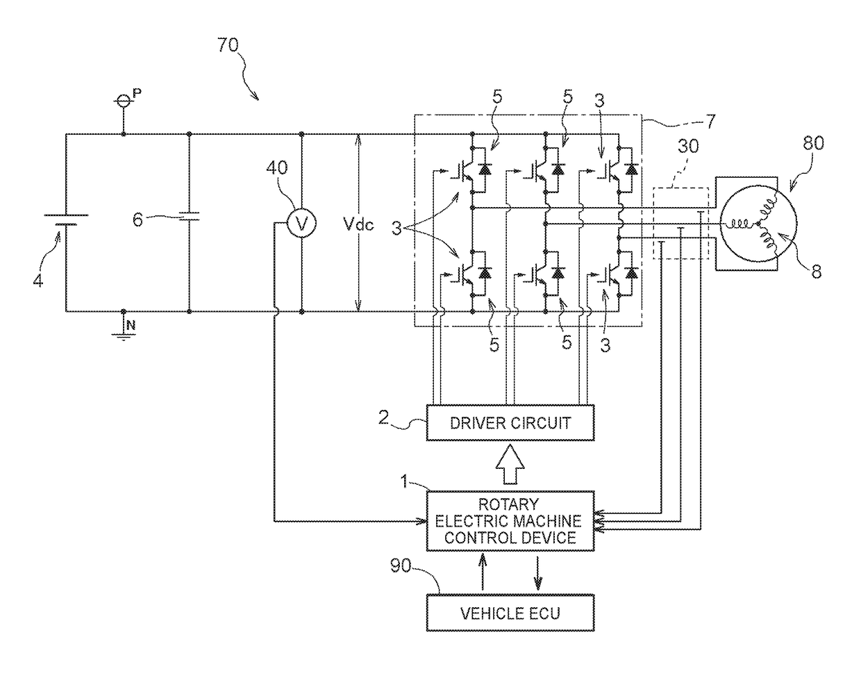
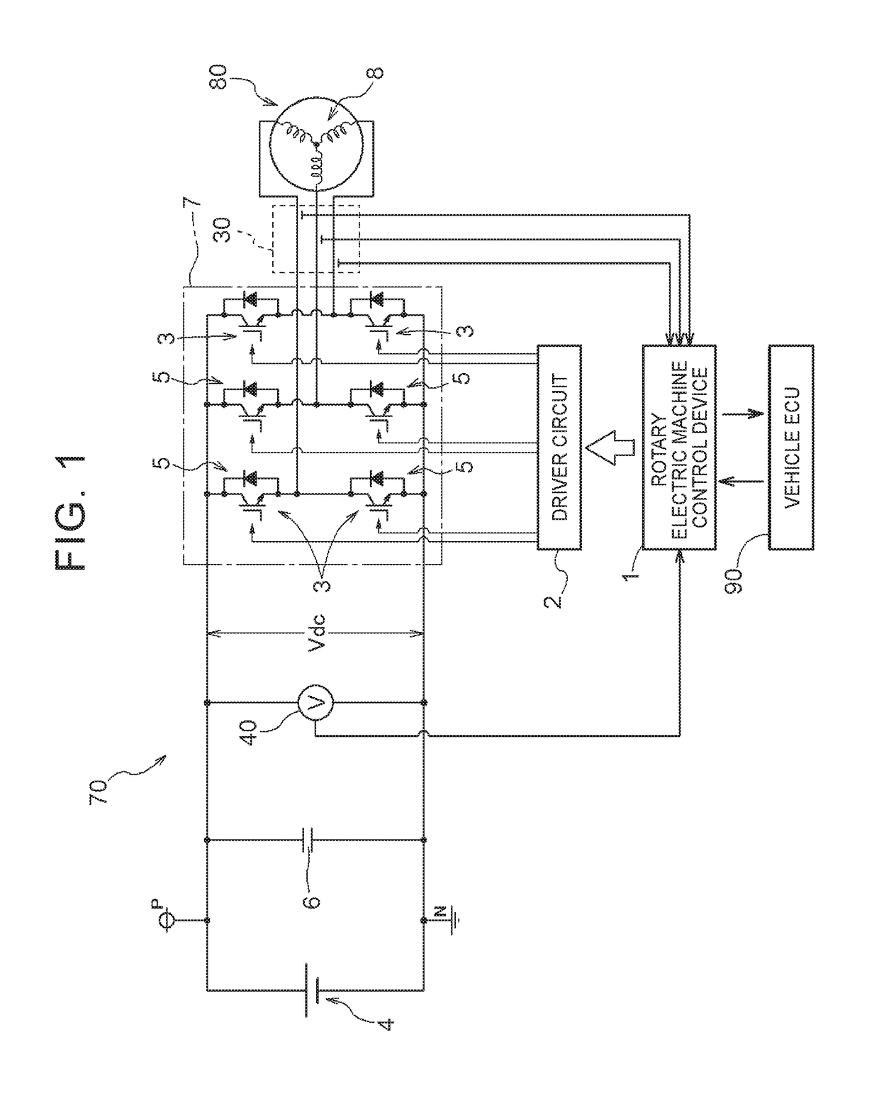
[0074]In one aspect, the rotary electric machine control device (1): controls a rotary electric machine (80) that includes a rotor in which a permanent magnet is disposed and that is driven via an inverter (7) that performs power conversion between AC power and DC power;
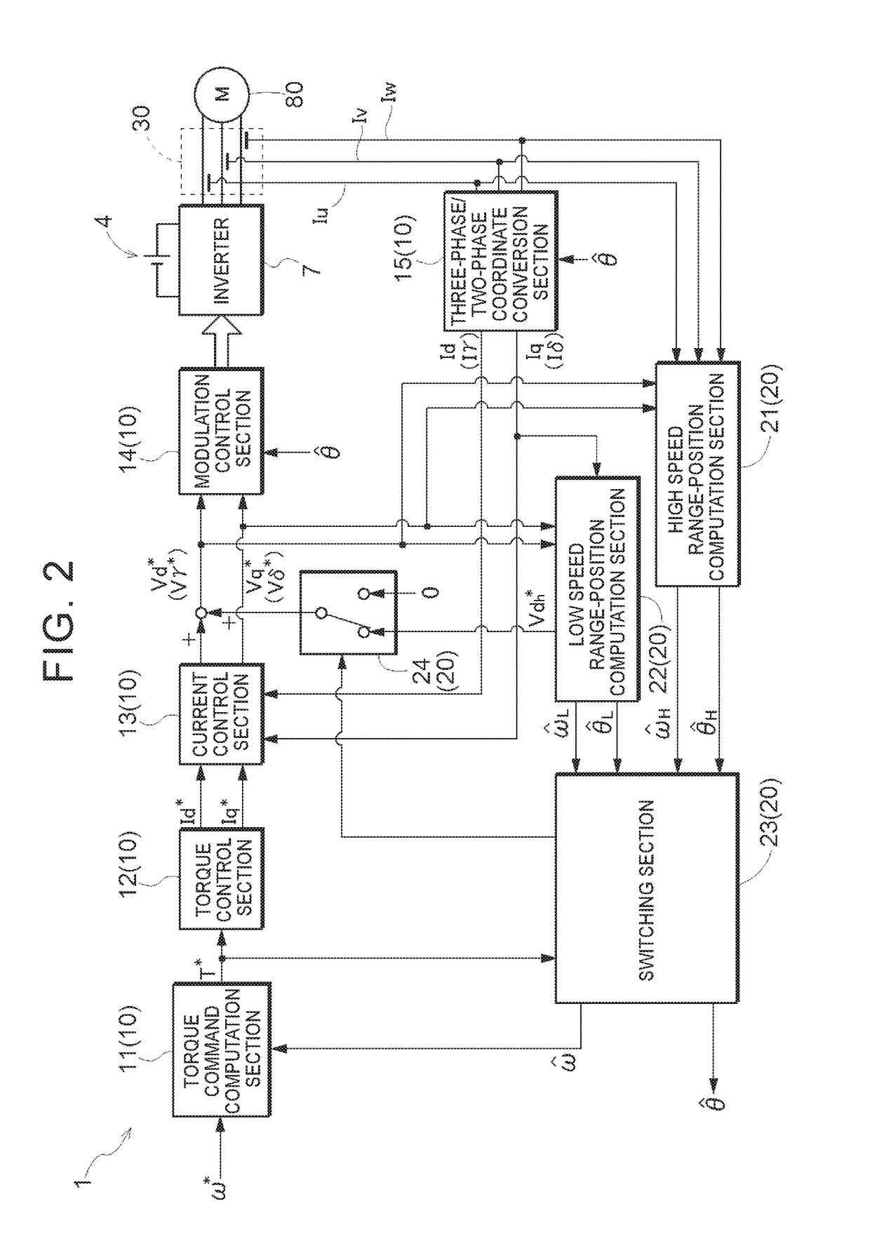
[0075]detects a magnetic pole position (θ) of the rotor through sensorless control;
[0076]performs current feedback control, using the magnetic pole position (θ), on the basis of a deviation between a current command (Id*, Iq*) and a feedback current from the rotary electric machine (80) in a d-q-axis vector coordinate system defined by a d-axis which extends in a direction of a magnetic field generated by the permanent magnet and a q-axis which is orthogonal to the d-axis;
[0077]performs dead-time compensation in which a start point and an end point of a...
PUM
 Abstract
Description
Claims
Application Information