A Toilet Including a Water Trap Having a Conical Part

Inactive Publication Date: 2015-12-10
CDUP
View PDF8 Cites 2 Cited by
  • Summary
  • Abstract
  • Description
  • Claims
  • Application Information

AI Technical Summary

Benefits of technology

[0005]The object of the present invention is to provide an improved toilet requiring less water flow for flush

Problems solved by technology

One disadvantage of a toilet bowl with tank is that it is bulky and takes much space.
One problem that must be solved with such kind of toilet is how to get a sufficiently efficient emptying of the water trap during a flush.
More specifical

Method used


Image

  • A Toilet Including a Water Trap Having a Conical Part
  • A Toilet Including a Water Trap Having a Conical Part
  • A Toilet Including a Water Trap Having a Conical Part

Examples


Embodiment Construction

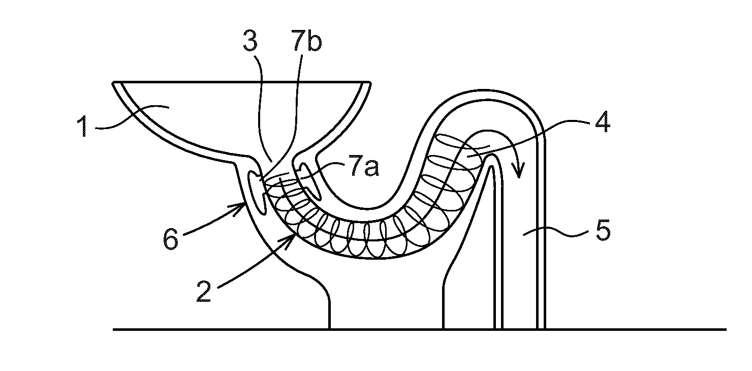
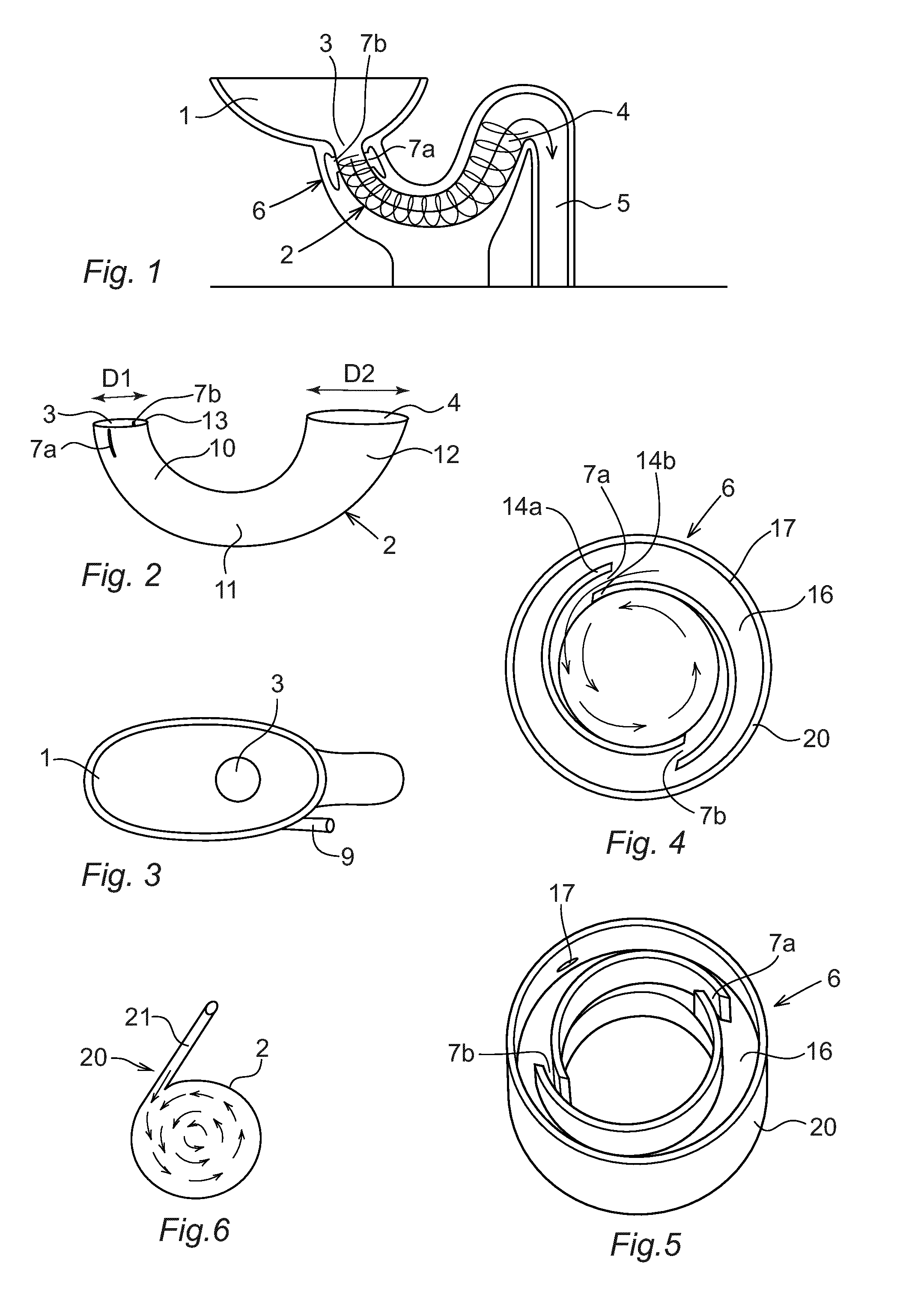
[0029]FIG. 1 shows a cross section cut through a toilet according to an embodiment of the invention. The toilet comprises a bowl 1, a water trap 2 in the form of a curved cone with an inlet 3 which is connected to the bowl, and an outlet 4 for connection to a sewer pipe 5, and a flushing system 6 arranged that upon activation, flush the water trap by generating a water vortex that travels towards the outlet. The sewer pipe 5 may be a part of toilet, or a separate part that is mounted in place. The flushing system 6 includes at least one nozzle. The embodiment shown in FIG. 1 has two nozzles 7a-b. The toilet bowl shape is preferably gently sloping towards the water trap inlet 3. The toilet is preferably made of porcelain, but may also be made of other materials such as metal sheet or plastic. In an alternative embodiment of the invention, all or at least part of the water trap inner wall is coated with a layer of hydrophobic material. Preferably greater portion of the inner wall is c...


PUM


Abstract

The present invention relates to a toilet comprising a bowl (1), a water trap (2) including a conical part (2) in the form of a curved cone with an inlet (3) connected to the bowl and an outlet (4), and a flushing system (6) comprising at least one nozzle (7a) adapted to flush clean the water trap by generating a vortex of water in the conical part. The conical part is designed with increasing diameter in a direction towards the outlet, wherein the diameter of the outlet of the conical part is larger than the diameter of the inlet of the conical part.

Description

FIELD OF THE INVENTION[0001]The present invention relates to a toilet comprising of a bowl, a water trap including a conical part in the form of a curved cone with an inlet connected to the bowl, and a flushing system disposed to flush the water trap by generating a water vortex in the water trap.PRIOR ART[0002]Traditionally designed toilets require a flow rate of about 50 liters / minute in order to cope with rinsing the water trap. As the water flow in the water supply pipes in typical households is typically 10 liters / minute, most toilets are provided with a tank that is filled with water between flushes. One disadvantage of a toilet bowl with tank is that it is bulky and takes much space. It is therefore desirable to have toilets without a tank which instead takes its flush water directly from the water supply pipe. One problem that must be solved with such kind of toilet is how to get a sufficiently efficient emptying of the water trap during a flush. More specifically the proble...

Claims


Application Information

Patent Timeline
IPC IPC(8): E03D11/08E03D5/00
CPCE03D5/00E03D11/08E03D3/00E03D2201/30
Inventor GRONHAUG, STEFAN
Owner CDUP
Why Eureka
Try Eureka