Ice water energy storage evaporator

An evaporator, ice water technology, applied in the direction of evaporator/condenser, heat exchanger shell, heat exchange equipment, etc., can solve the problem that the evaporator volume cannot be made too large, energy loss, and high cost of antifreeze, reaching The effect of reducing ice blockage, reducing energy loss and reducing pump power

Inactive Publication Date: 2012-02-01
ZHEJIANG YAONENG TECH
View PDF6 Cites 0 Cited by
  • Summary
  • Abstract
  • Description
  • Claims
  • Application Information

AI Technical Summary

Problems solved by technology

[0004] Due to the high cost of antifreeze, antifreeze has a certain corrosive effect on the refrigeration unit, and the addition of antifreeze will affect the water quality. Therefore, in practice, basically no antifreeze is added to the water refrigerated by the refrigeration unit.
After years of use, it has been found that due to structural limitations, the above evaporator can only cool the water without adding antifreeze to 5°C at most. Once the temperature of the water is lower than 5°C, the evaporator will freeze and block. , and eventually cause the evaporator to burst and be scrapped. This cooling limit greatly reduces the heat exchange efficiency of the evaporator, so that the heat exchange between the refrigerant medium and water cannot be completely carried out. In order to ensure the normal operation of the compressor, a liquid-gas separator must be connected between the evaporator and the compressor, which not only increases the manufacturing cost of the refrigeration unit, prolongs the circulation route of the refrigeration medium, and reduces the circulation speed , but also cause unnecessary loss of part of the energy
[0005] However, it has been found through experiments that the circulation of water forms a type of helical circulation under the limitation of the dislocation of the gaps 151' of each partition plate, and the water enters the inner cavity 14 under the action of centrifugal force and the obstruction of the outer copper tube 2'. 'The water in the center is relatively small and the flow speed is slow, and the closer to the center this phenomenon is more obvious, and the less water flow, the slower the flow speed, the easier it is to freeze
In addition, due to the seamless connection between the copper pipe 2' and the partition plate 15', a certain dead angle will be formed during the water circulation process, which greatly hinders the flow of water and is prone to freezing
The above two experiments show that the volume of the evaporator cannot be made too large. The larger the volume, the more prominent the problem of icing in the center and the lower the heat exchange efficiency. However, this structural limitation of the evaporator has resulted in the current high-power refrigeration unit. bottleneck

Method used


Image

  • Ice water energy storage evaporator
  • Ice water energy storage evaporator
  • Ice water energy storage evaporator

Examples


Embodiment Construction

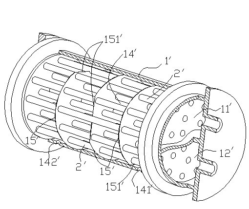
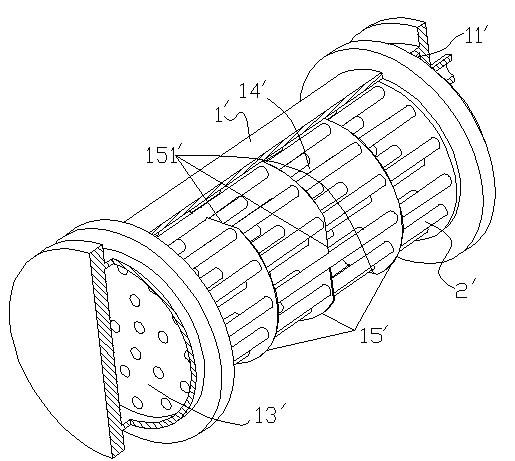
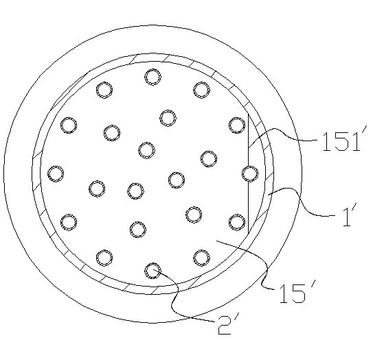
[0024] Such as Figure 4-6 As shown, an ice water energy storage evaporator, the whole evaporator includes a shell 1, one end of the shell 1 is provided with a completely separated refrigerant medium liquid inlet cavity 11 and a refrigerant medium air outlet cavity 12, on the other side of the shell 1 One end is provided with a refrigerant medium transition cavity 13 . The cooling copper tubes 2 are evenly distributed in the housing cavity 14 except for the central part, wherein the copper tubes 2 in the upper part of the housing cavity 14 are connected to the cooling medium liquid inlet cavity 11 and the cooling medium transition cavity 13, and the lower part of the casing cavity 14 is Half of the copper pipe 2 connects the refrigerant medium transition chamber 13 and the refrigerant medium outlet chamber 12 . One end of the housing cavity 14 is provided with a liquid inlet 141 , and the other end is provided with a liquid outlet 142 . Simultaneously, the whole inner chambe...


PUM


Abstract

The invention discloses an ice water energy storage evaporator which comprises a shell, a refrigerating medium liquid inlet cavity, a refrigerating medium air outlet cavity, a refrigerating medium transitional cavity, a cooling copper tube and a plurality of flow isolating plates with gaps, wherein the refrigerating medium liquid inlet cavity and the refrigerating medium air outlet cavity are arranged at one end of the shell; the refrigerating medium transitional cavity is arranged at the other end of the shell; the cooling copper tube is arranged in the cavity of the shell; and the plurality of flow isolating plates with the gaps divide the cavity of the shell into a plurality of cavities; and the cooling copper tube is not arranged in a spare position of the cavity; and water circulating direct-through holes are arranged on the flow isolating plates of the spare position of the cavity. The ice water energy storage evaporator breaks through the bottleneck that when the traditional evaporator is refrigerated to 5 DEG C, an evaporating tube gradually freezes from an inner ring to an outer ring; the ice water energy storage evaporator can directly refrigerate water to 0 DEG C without icing and achieves the high efficiency refrigeration effect which can not be achieved by the traditional evaporator.

Description

technical field [0001] The invention relates to an evaporator, in particular to an ice water energy storage evaporator. Background technique [0002] At present, the traditional evaporator structure such as Figure 1-3 As shown, the entire evaporator includes a shell 1', one end of the shell 1' is provided with a completely separated refrigerant medium liquid inlet chamber 11' and a refrigerant medium air outlet chamber 12', and the other end of the shell is provided with a refrigerant medium transition Cavity 13'; while cooling copper tubes 2' are evenly distributed in the entire housing cavity 14', and the distance between two adjacent copper tubes 2' is equal, wherein the copper tubes 2' in the upper part of the housing cavity 14' Connect the refrigerant medium liquid inlet chamber 11' and the refrigerant medium transition chamber 13', and the copper pipe 2' in the lower part of the housing inner chamber 14' connects the refrigerant medium transition chamber 13' and the r...

Claims


Application Information

Patent Timeline
Patent Type & Authority Applications(China)
IPC IPC(8): F25B39/02F28F9/24
Inventor 余小兵
Owner ZHEJIANG YAONENG TECH
Why Eureka
Try Eureka