Systems and methods for egr control

a technology of egr control and system, applied in the direction of electric control, ignition automatic control, machines/engines, etc., can solve the problems of torque unevenness, durability issues, and inability to use diverter valves, so as to reduce engine knock, throttling losses, in-cylinder heat losses, and nox emissions. , the effect of reducing engine knock

Inactive Publication Date: 2015-12-10
FORD GLOBAL TECH LLC
View PDF1 Cites 41 Cited by
  • Summary
  • Abstract
  • Description
  • Claims
  • Application Information

AI Technical Summary

Benefits of technology

[0002]Engines may be configured with exhaust gas recirculation (EGR) systems to divert at least some exhaust gas from an engine exhaust manifold to an engine intake manifold. 40 By providing a desired engine dilution, such systems reduce engine knock, throttling losses, in-cylinder heat losses, as well as NOx emissions. As a result, fuel economy is improved, especially at higher levels of engine boost. Engines have also been configured with a sole cylinder (or cylinder group) that is dedicated for pr

Problems solved by technology

However, the use of diverter valves may be cost prohibitive.
In addition, they may have durability issues.
However, the inventors herein have recognized potential issues with the above approach.
As an example, the deactivation of the dedicated EGR cylinder may lead to torque unevenness.
For example, even after fuel has been shut off in the dedicated EGR cylinder, due to delays in manifold filling, there may be a corresponding delay in purging EGR from the engine intake.
As yet another example, the higher amount of fresh air received during

Method used


Image

  • Systems and methods for egr control
  • Systems and methods for egr control
  • Systems and methods for egr control

Examples


Embodiment Construction

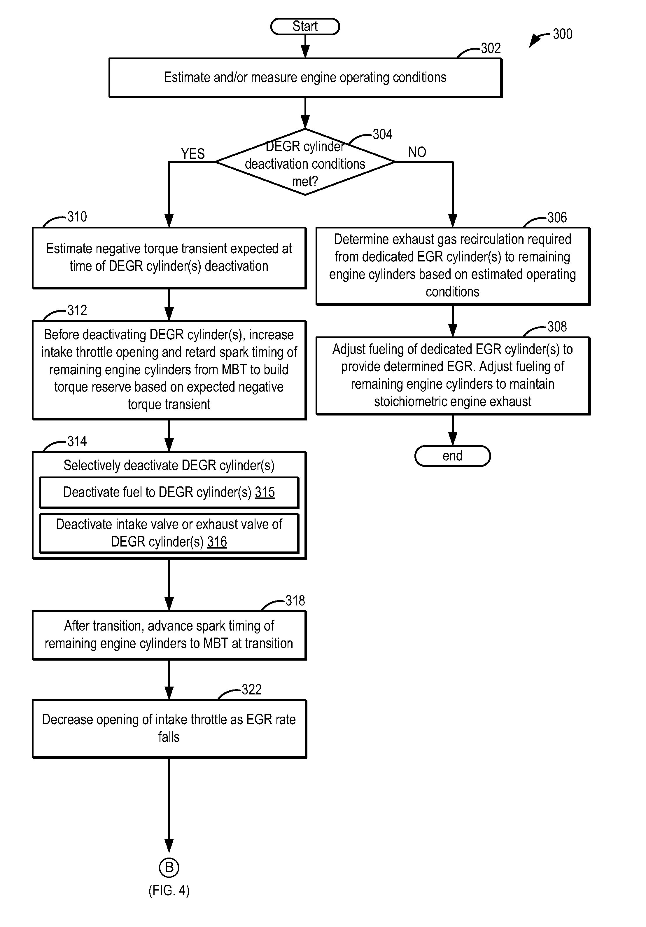
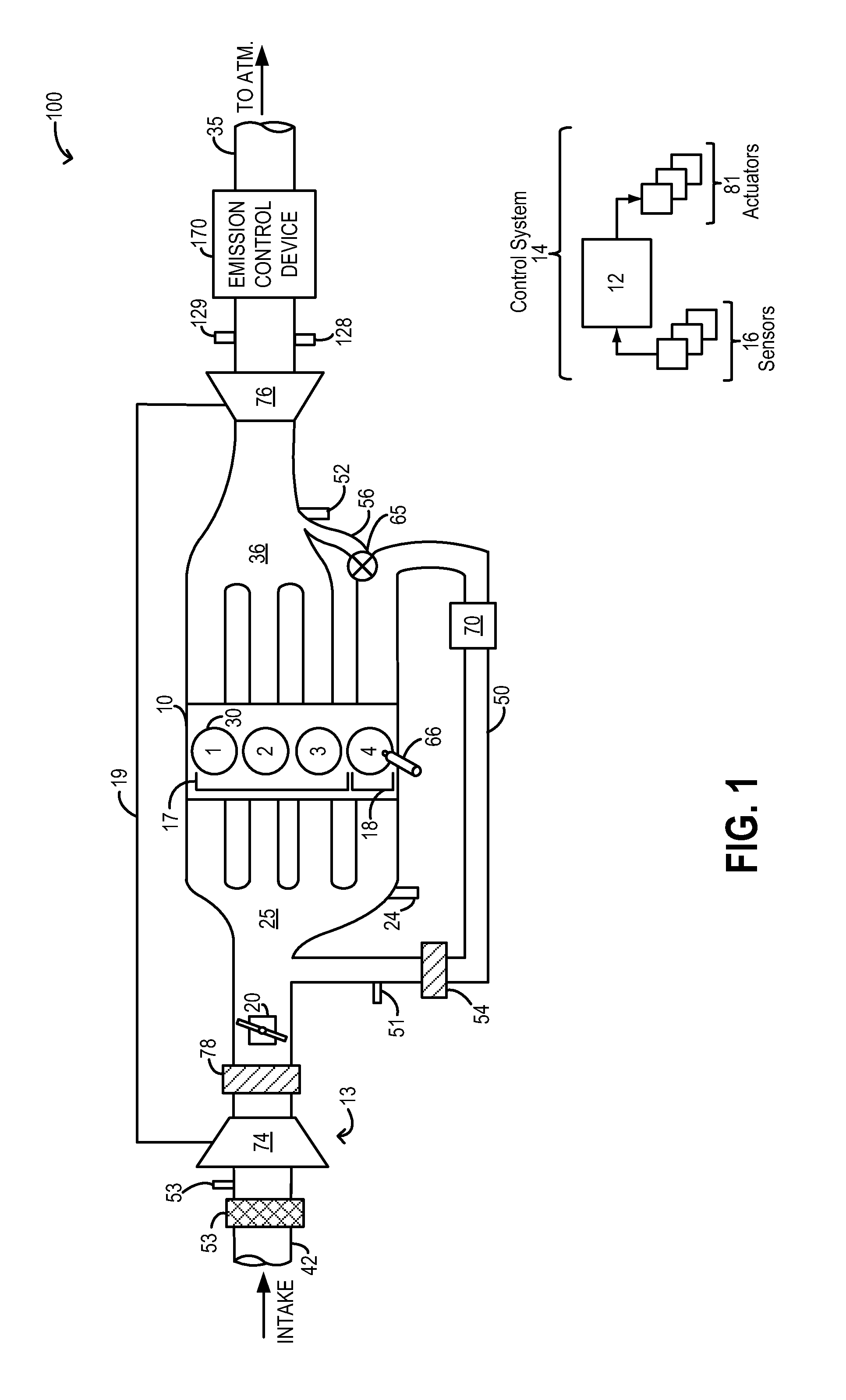
[0016]The present description is related to EGR flow control on an engine operating with highly diluted cylinder mixtures, such as the engine systems of FIGS. 1-2. The engine cylinder mixtures may be diluted using recirculated exhaust gases (EGR) that are byproducts of combusting air-fuel mixtures. A controller may be configured to perform a control routine, such as the routine of FIGS. 3-4 to adjust fueling of the dedicated EGR cylinder group in response to an increase or decrease in EGR demand. In addition, the controller may adjust one or more engine actuators, such as spark timing and valve timing, while varying the EGR flow from the dedicated EGR cylinder group to reduce torque transients. An example adjustment for torque transient control is shown with reference to FIG. 5.

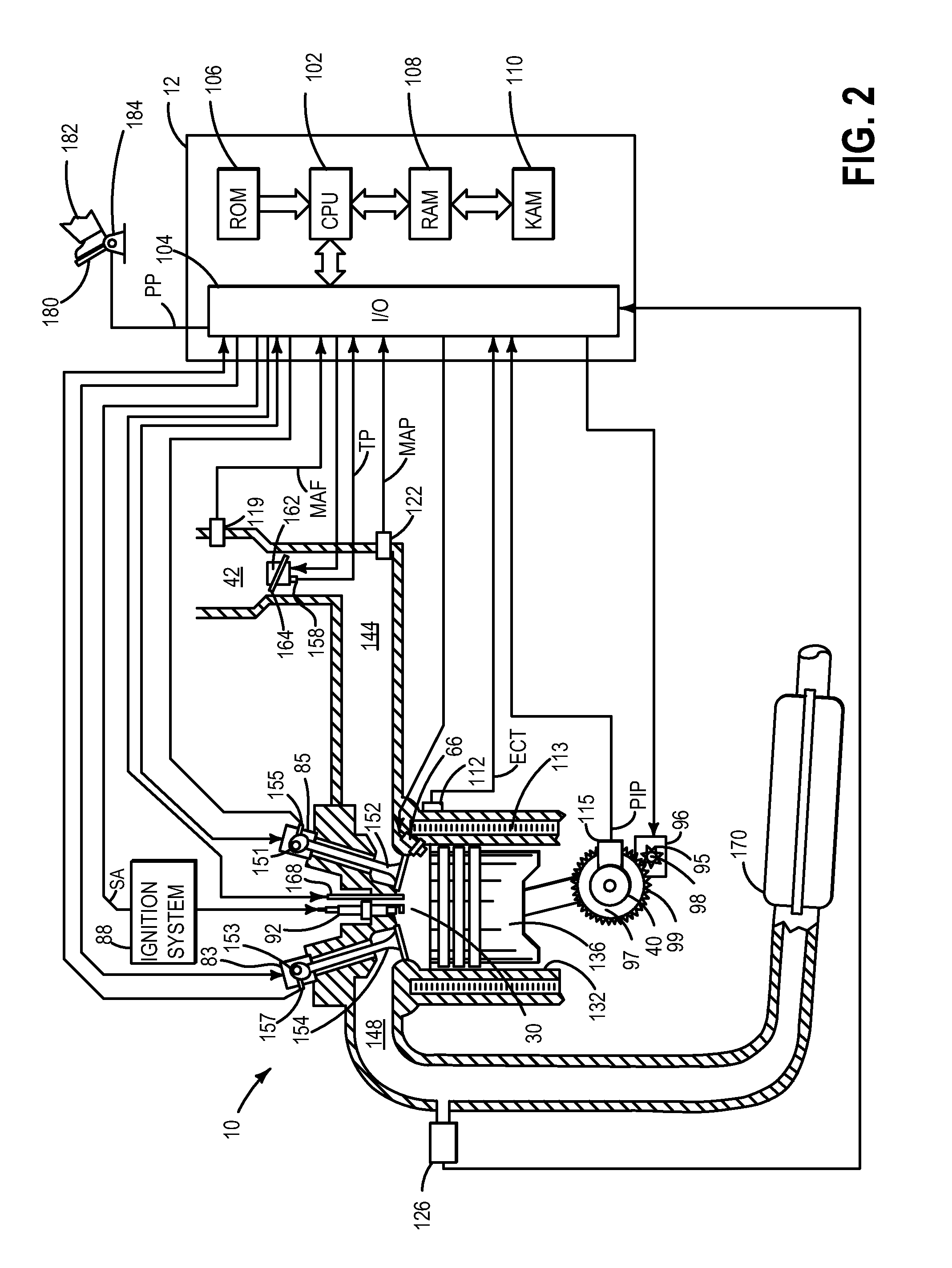
[0017]FIG. 1 schematically shows aspects an example engine system 100 including an engine 10 with four cylinders (1-4). As elaborated herein, the four cylinders are arranged as a first cylinder group 17 consi...


PUM


Abstract

Methods and systems are provided for reducing torque transients experienced when a dedicated EGR cylinder is deactivated to reduce EGR. Before deactivating the dedicated cylinder, an intake throttle position and spark timing of remaining engine cylinders is adjusted to build-up torque reserve in anticipation of a negative torque transient at deactivation. Then, the throttle position or spark timing is adjusted to reduce torque when a positive torque transient is expected.

Description

FIELD[0001]The present description relates to systems and methods for improving EGR transients in engine systems configured with a dedicated cylinder group for providing external EGR to other engine cylinders.BACKGROUND AND SUMMARY[0002]Engines may be configured with exhaust gas recirculation (EGR) systems to divert at least some exhaust gas from an engine exhaust manifold to an engine intake manifold. 40 By providing a desired engine dilution, such systems reduce engine knock, throttling losses, in-cylinder heat losses, as well as NOx emissions. As a result, fuel economy is improved, especially at higher levels of engine boost. Engines have also been configured with a sole cylinder (or cylinder group) that is dedicated for providing external EGR to other engine cylinders. Therein, all of the exhaust from the dedicated cylinder group is recirculated to the intake manifold. As such, this allows a substantially fixed amount of EGR to be provided to engine cylinders at most operating c...

Claims


Application Information

Patent Timeline
IPC IPC(8): F02D41/00F02D17/02F02M25/07F02P5/04
CPCF02D41/0002F02P5/045F02D2041/0017F02M25/0749F02D17/02F02D37/02F02D41/0065F02D41/008F02D41/0087F02D2041/0012F02D2250/21F02M26/43F02P5/1504F02P5/1516Y02T10/40
Inventor LEONE, THOMAS G.SHELBY, MICHAEL HOWARDGLUGLA, CHRIS PAULCZEKALA, MICHAEL DAMIANSTYLES, DANIEL JOSEPH
Owner FORD GLOBAL TECH LLC
Why Eureka
Try Eureka