
Solar turbo pump - hybrid heating-air conditioning and method of operation

a technology of solar energy and hybrid heating, applied in the direction of heat pumps, machines using solar energy, lighting and heating apparatus, etc., can solve the problems of failure to teach the use of solar energy pump on the solar energy turbine drive system, failure to disclose thermal storage or any need for thermal storage, and failure to disclose the amount of work needed. to achieve the effect of reducing the electrical consumption of heating

Active Publication Date: 2015-12-10
SOLTAIR HLDG LLC
View PDF6 Cites 7 Cited by
  • Summary
  • Abstract
  • Description
  • Claims
  • Application Information

AI Technical Summary

Benefits of technology

The present invention is a renewable energy solution for heating and air conditioning systems. It reduces electrical consumption by using the compressor only on bad weather days. The system can provide heating and air conditioning every day for 24 hours a day, depending on the ability to use the sun to heat the refrigerant. The invention eliminates the need for conventional power sources and provides energy from the sun using a turbocharged pump and solar collector. It also includes thermal energy storage to provide energy when there is no sufficient sun or when solar energy is not available. The invention can be added to existing HVAC systems or integrated into a new system. In cold weather climates, the invention provides a solar powered heat source using a solar turbo-collector and a condenser / evaporator system.

Problems solved by technology

The disclosure fails to teach the use of a pump on the solar turbine drive system which prohibits the system from generating electricity during the Solar driven HVAC process.
The disclosure further fails to define or teach the amount of work needed to drive the compressor or teach the energy balance required to ensure operation.
The disclosure also fails to disclose thermal storage or any need for thermal storage.

Method used


Image

  • Solar turbo pump - hybrid heating-air conditioning and method of operation
  • Solar turbo pump - hybrid heating-air conditioning and method of operation
  • Solar turbo pump - hybrid heating-air conditioning and method of operation

Examples


Embodiment Construction

[0055]While the present invention is susceptible of embodiment in various forms, there is shown in the drawings and will hereinafter be described a presently preferred, albeit not limiting, embodiment with the understanding that the present disclosure is to be considered an exemplification of the present invention and is not intended to limit the invention to the specific embodiments illustrated.

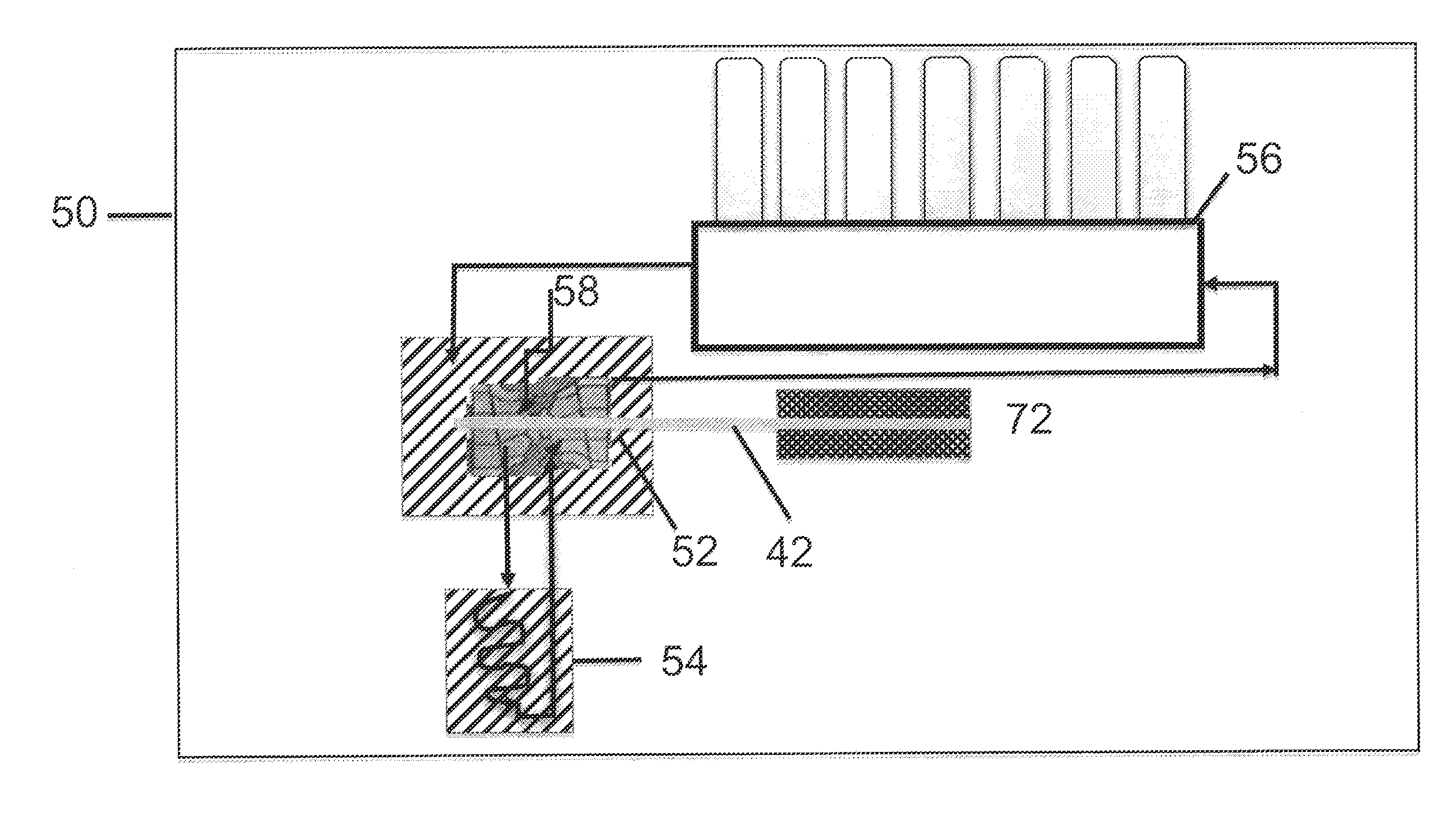
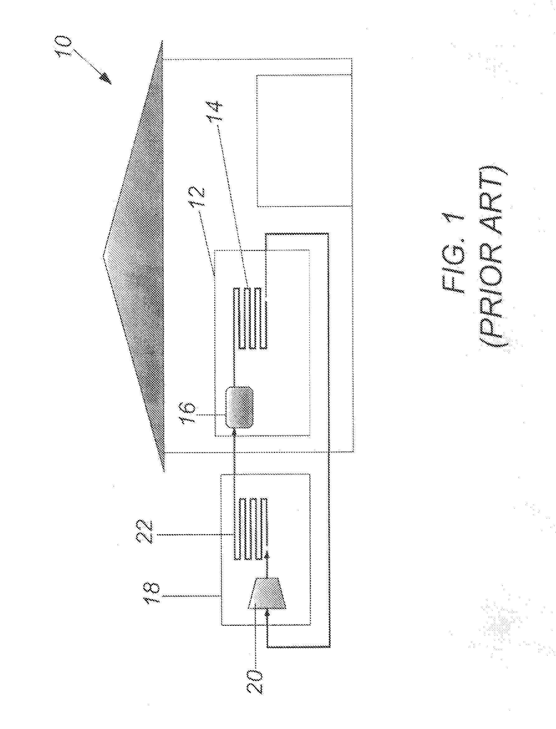
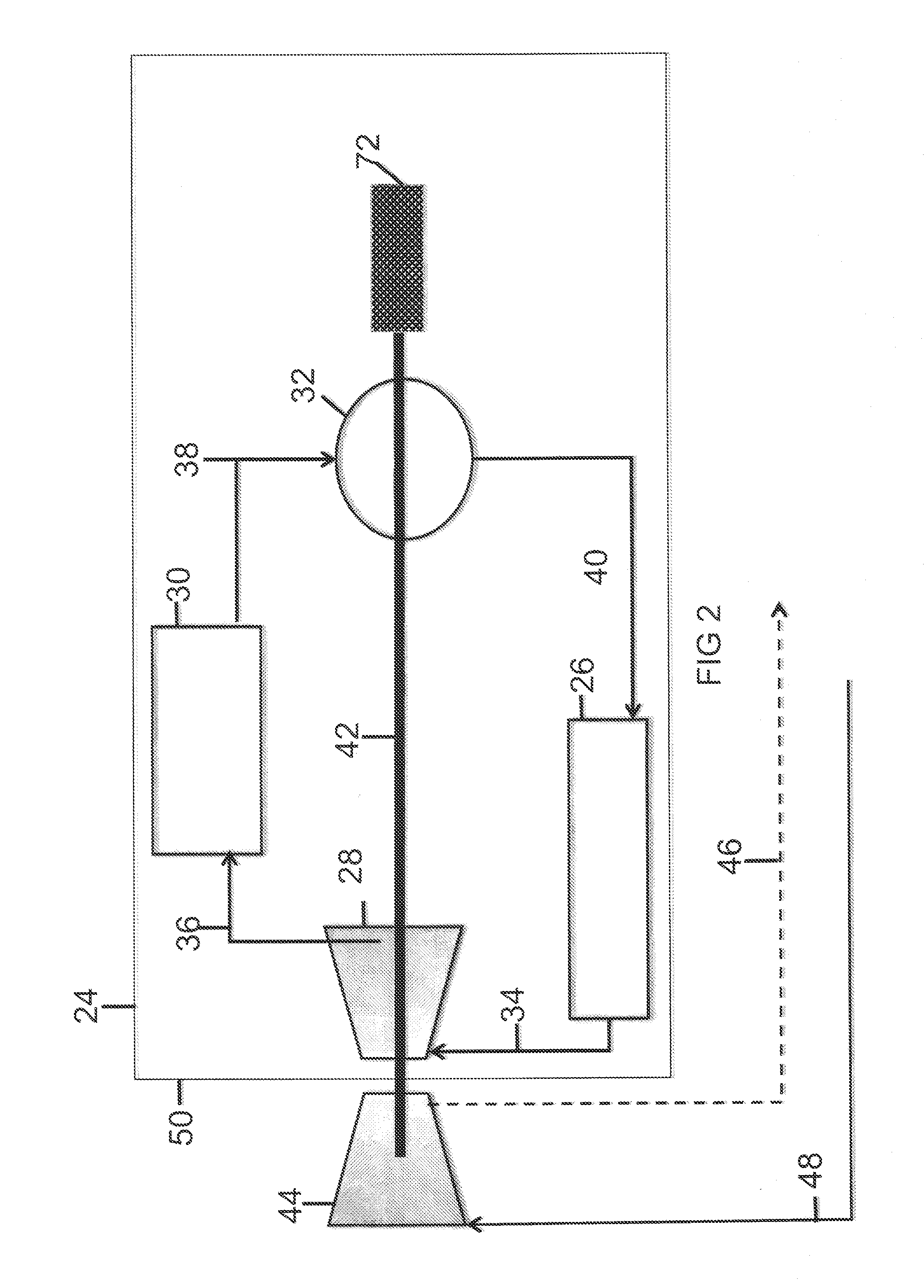
[0056]FIGS. 1-20, which are now referenced and have been revised, illustrate the prior art, the present invention, and the manner in which the present invention is operated. Upon determination of the correct heating / air conditioning requirements, the system of the present invention can be attached to a users existing air handling heating / air conditioning system. The present system utilizes a solar refrigerant turbocharger and pump in conjunction with a solar concentrator / collector 26 to harness the suns energy. A liquid pump 32 within the solar turbocharger boosts the refrigerant pressures i...


PUM


Abstract

A closed loop system utilizing a solar refrigerant turbocharger and pump in conjunction with a solar collector to operate a heating and cooling system for a building by utilization of a renewable energy source. The liquid pump within the solar turbocharger is used to boost the refrigerant pressures into the solar collector, the refrigerant absorbs heat inside the solar collector and changes phase from a liquid to a vapor. The vapor is expanded across the turbine causing the turbine to spin. The ability of the refrigerant to change phase or flash from a liquid to a vapor is due to the solar energy that is transferred from evacuated tubes into the solar collector manifold and into the refrigerant. The gas is routed to the solar turbo pump turbine to drive the compressor and liquid pump. The resulting fluid gas leaving the turbine is routed to the condenser for normal operation.

Description

PRIORITY CLAIM[0001]In accordance with 37 C.F.R. 1.76, a claim of priority is included in an Application Data Sheet filed concurrently herewith. Accordingly, the present invention claims priority as a continuation-in-part of U.S. patent application Ser. No. 13 / 415,108 filed Mar. 8, 2012, which claims the benefit of priority of U.S. Provisional Patent Application No. 61 / 450,439, filed on Mar. 8, 2011, the entire contents of which is hereby expressly incorporated herein by reference.FIELD OF THE INVENTION[0002]This invention is directed to using renewable energy, such as solar energy, to operate a heating and cooling system, in particular to an apparatus and method of operating a heating and cooling system by using renewable energy, turbocharging, and storing the renewable energy to provide twenty-four hour, seven days a week, heating and air conditioning.BACKGROUND OF THE INVENTION[0003]It is well documented that the world is searching for renewable, “Green Energy” solutions to power...

Claims


Application Information

Patent Timeline
Patent Type & Authority Applications(United States)
IPC IPC(8): F25B27/00F25B30/02
CPCF25B30/02F25B27/005F01K15/00F03G6/065Y02A30/272Y02B10/20Y02E10/46
Inventor POERIO, WAYNE
Owner SOLTAIR HLDG LLC
Learn More