Automatic pressure-adjusting leak detecting apparatus and method

a leak detection and automatic adjustment technology, applied in the direction of measurement devices, instruments, structural/machine measurement, etc., can solve the problems of engine power loss, increased fuel consumption, and the operation of turbo and other boosted engine systems at significantly higher system pressure, so as to achieve gradual increase of the pressure of the regulated air

Active Publication Date: 2015-12-10
CPS PRODS
View PDF2 Cites 9 Cited by
  • Summary
  • Abstract
  • Description
  • Claims
  • Application Information

AI Technical Summary

Benefits of technology

[0011]At the start of a leak test, the controller opens the solenoid and causes either a heater from the smoke generator to be energized or a fluid pump and atomizing nozzle (which has no heater) to be activated. The pressure regulator is adjusted by the controller so that the pressure of the regulated air is gradually increased. The flow rate measured by the flow transducer through which the regulated air flows from the pressure regulator to the smoke generator rises rapidly until a pre-determined optimal flow rate is achieved. The optimal flow rate is then held constant (regardless of the rising pressure to which the pressure regulator is adjusted) until an optimal operator-set test pressure is achieved at which time the pressure regulator and system pressures measured by the first and second pressure transducers at the inlet and outlet sides of the solenoid are equalized. With the system under test fully pressurized, the pressure of the regulator is held constant such that the regulated air supplied to the smoke generator is reduced. Thus, the flow rate measured by the flow transducer is correspondingly decreased during which time the system being tested is visually inspected for any smoke which escapes therefrom to indicate a leak. At the conclusion of the leak test, the controller causes the solenoid to close and the heater of the smoke generator to be de-energized or the fluid pump and atomizing nozzle to be deactivated. The system pressure (at the outlet side of the solenoid measured by the second pressure transducer) is then monitored for decay which is also indicative of the presence and size of a leak in the system being tested for leaks.

Problems solved by technology

Engine air leaks create engine loss of power and increased fuel consumption.
However, turbo and other boosted engine systems operate at significantly higher system pressure than non-turbo or non-boosted systems.
These systems will commonly experience air leaks at high system pressures.
Therefore, in the case of smoke generating leak detectors, using low pressure smoke generators cannot create sufficient pressure in the engine systems in order to simulate the engine's operating pressures.
Consequently, it would be quite difficult to find leaks in such higher pressure systems using a low pressure device.
In this same regard, less visible smoke exits the system making it harder for the technician to detect the leak site.
Consequently, the density of the smoke which exits the system is decreased which also makes it difficult for the technician to identify the leak site.

Method used


Image

  • Automatic pressure-adjusting leak detecting apparatus and method
  • Automatic pressure-adjusting leak detecting apparatus and method
  • Automatic pressure-adjusting leak detecting apparatus and method

Examples


Embodiment Construction

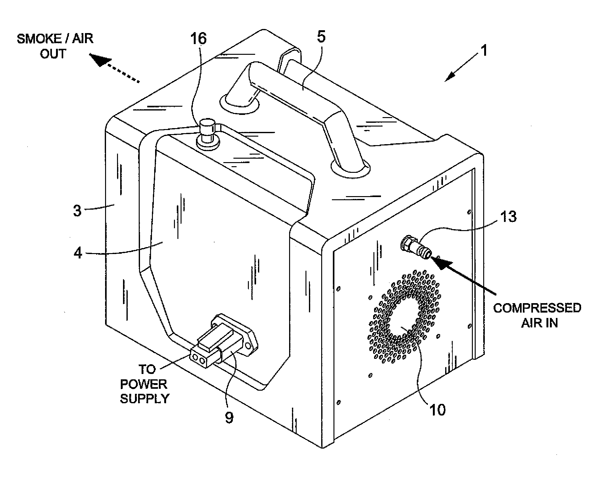
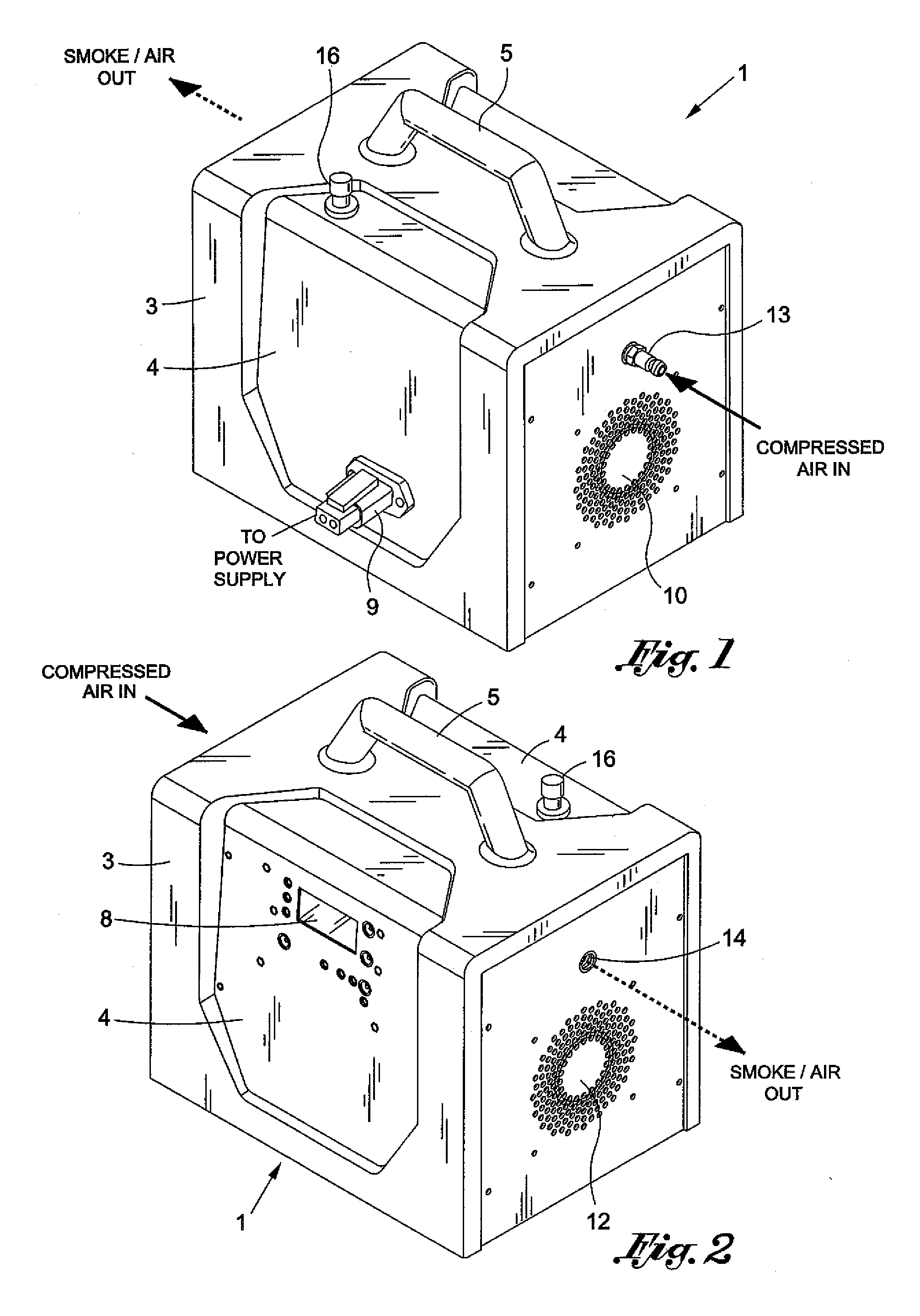
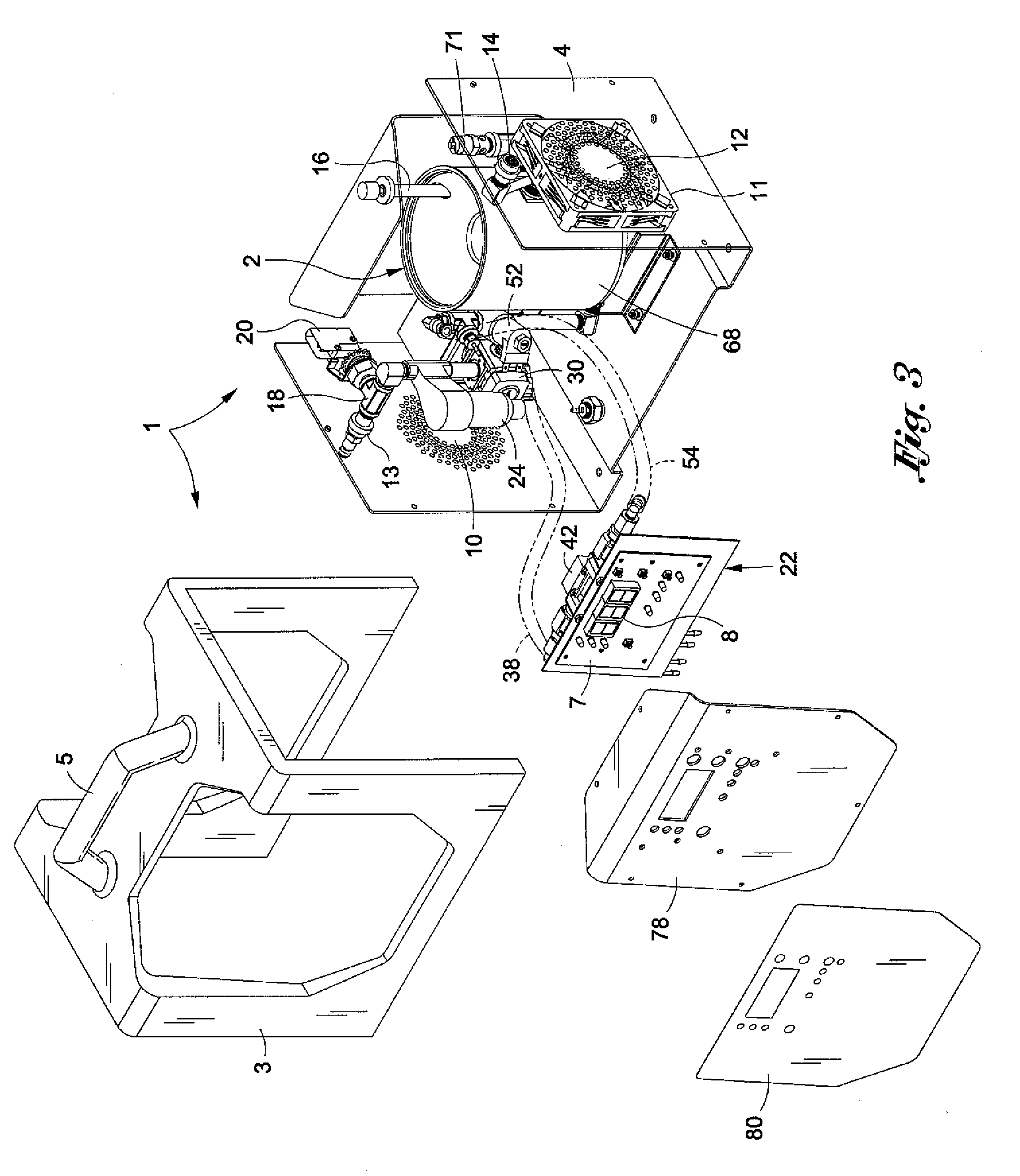
[0019]An automatic pressure-adjusting leak detecting apparatus 1 having a smoke generator 2 that is capable of producing visible vapor (commonly known in the trade and referred to below as “smoke”) by which the presence and location of a leak in a closed fluid system can be reliably detected is disclosed while referring initially to FIGS. 1 and 2 of the drawings. The leak detecting apparatus 1 to generate the aforementioned smoke has particular application for detecting leaks in fluid systems of motor vehicles that operate at a variety of high pressures depending upon the vehicles. By way of example only, one such high-pressure operating fluid system with which the leak detecting apparatus 1 can be used to test for leaks is the engine system of a turbo-charged motor vehicle.

[0020]As will be explained in greater detail hereinafter, the leak detecting apparatus 1 is adapted to controllably produce an ideal supply of thick, dense smoke at a particular flow rate and pressure as are requ...


PUM


Abstract

A leak detecting apparatus and method by which a regulated supply of gas is delivered from an adjustable pressure regulator to a smoke generator so that smoke generated within the smoke generator and carried to a fluid system being tested for leaks is at optimal density throughout the pressure range. The leak detecting apparatus and method have particular application for testing high pressure operating systems (e.g., the engine of a turbo-charged motor vehicle). A flow transducer measures the rate at which the regulated supply of gas flows to the smoke generator. First and second pressure transducers measure the pressure of the regulated gas and the pressure of the system being tested for leaks. The system under test is visually inspected for leaks after the pressure regulator is adjusted to a pressure to create an optimal maximum flow rate and the pressures measured by the first and second pressure transducers are equalized.

Description

BACKGROUND OF THE INVENTION[0001]1. Field of the Invention[0002]This invention relates to an automatically adjustable, microcontroller controlled leak detecting apparatus and method for delivering smoke at an optimal smoke density throughout the pressure range so as to provide a reliable visual indication of the presence and location of a leak. The foregoing is accomplished by delivering a regulated supply of gas (e.g., compressed air) at an optimal pressure and flow rate from a pressure regulator to a smoke generator to be mixed with the gas and carried thereby to a fluid system under test. The leak detecting apparatus and method herein disclosed have particular application for testing systems (e.g., a turbo-charged engine of a motor vehicle) that operate at high pressures.[0003]2. Background Art[0004]Because of concerns for the environment, and due to excessive engine fuel consumption, it has become increasingly important to be able to test the integrity of the engine of a motor v...

Claims


Application Information

Patent Timeline
Patent Type & Authority Applications(United States)
IPC IPC(8): G01M3/04
CPCG01M3/04G01M3/20G01M3/025
Inventor MCCOLLOM, GREGORY M.MURASHIE, EDWARD A.HALMBACHER, GARY W.
Owner CPS PRODS
Why Eureka
Try Eureka