Coil structure and power source device

Inactive Publication Date: 2015-12-10
PANASONIC INTELLECTUAL PROPERTY MANAGEMENT CO LTD
View PDF7 Cites 3 Cited by
  • Summary
  • Abstract
  • Description
  • Claims
  • Application Information

AI Technical Summary

Benefits of technology

[0006]One non-limiting and exemplary embodiment provides a coil structure

Problems solved by technology

The inventors of the present invention conducted a study on a power converter circuit in which a conventional coil structure is incorporated and found that the conventi

Method used


Image

  • Coil structure and power source device
  • Coil structure and power source device
  • Coil structure and power source device

Examples


first embodiment

[0080]The inventors of the present invention developed a coil structure that can properly solve the above problems. In the First Embodiment, the design principle of the coil structure is described.

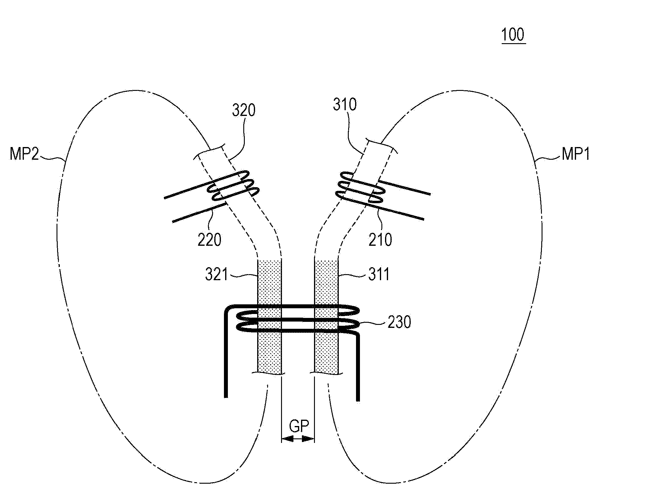
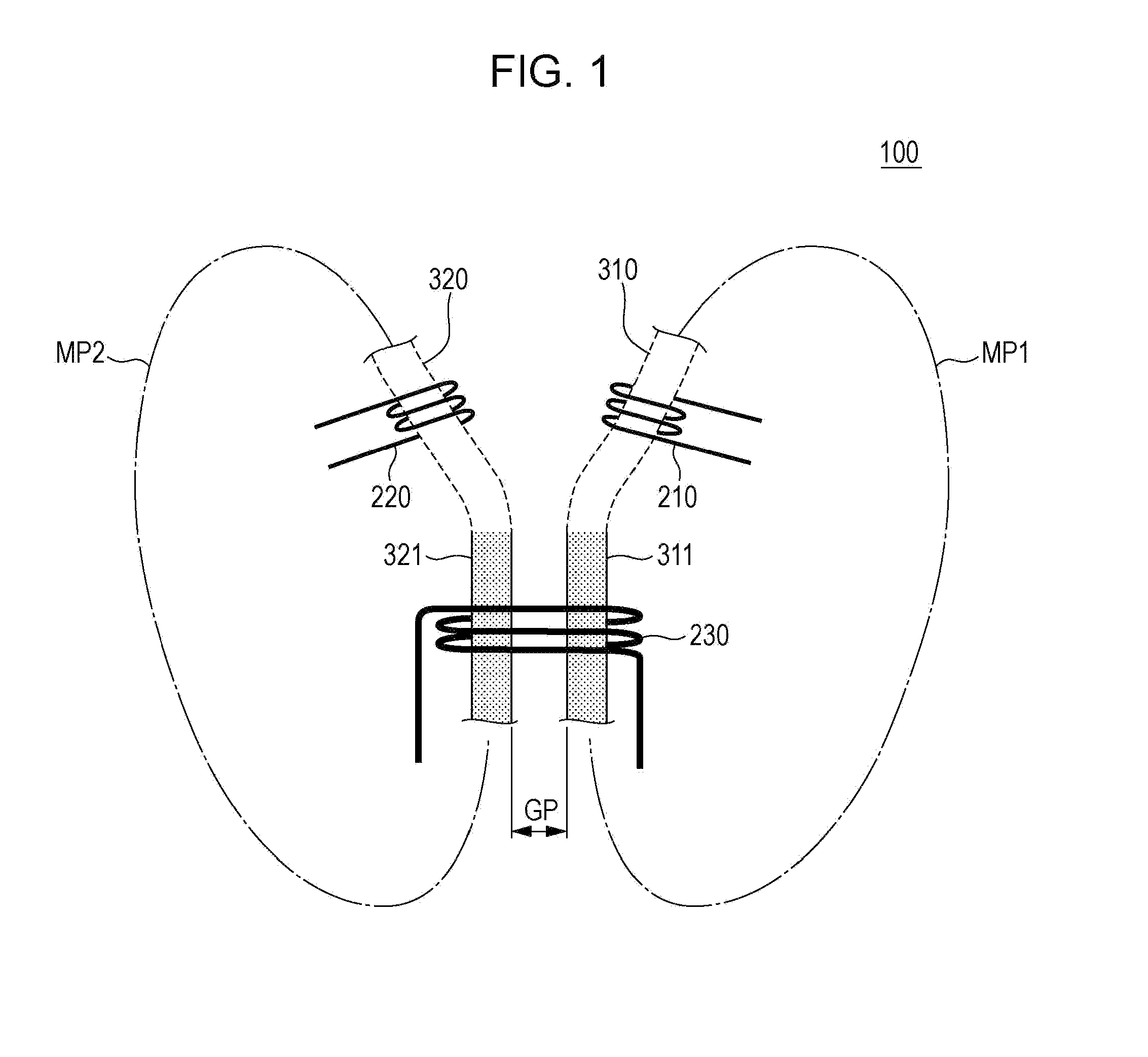
[0081]FIG. 1 is a concept diagram of a coil structure 100 of the First Embodiment. The coil structure 100 is described below with reference to FIG. 1.

[0082]The coil structure 100 includes a first coil 210, a second coil 220, a third coil 230, an annular first core 310, and an annular second core 320. The first coil 210 and the second coil 220 are used as primary coils. The third coil 230 is used as a secondary coil.

[0083]The first core 310 is made of a magnetic material. The first coil 210 is wound around part of the first core 310. The first core 310 defines an annular magnetic path MP1 along which a magnetic flux occurring due to power supply to the first coil 210 flows. The designer of the coil structure 100 may give the first core 310 any of various shapes. For example, the first core ...

second embodiment

[0090]The inventors of the present invention conducted a study on a relationship between the coupling coefficient between two primary coils and a gap between two annular cores. In the Second Embodiment, a proper size of the gap between the two annular cores is described.

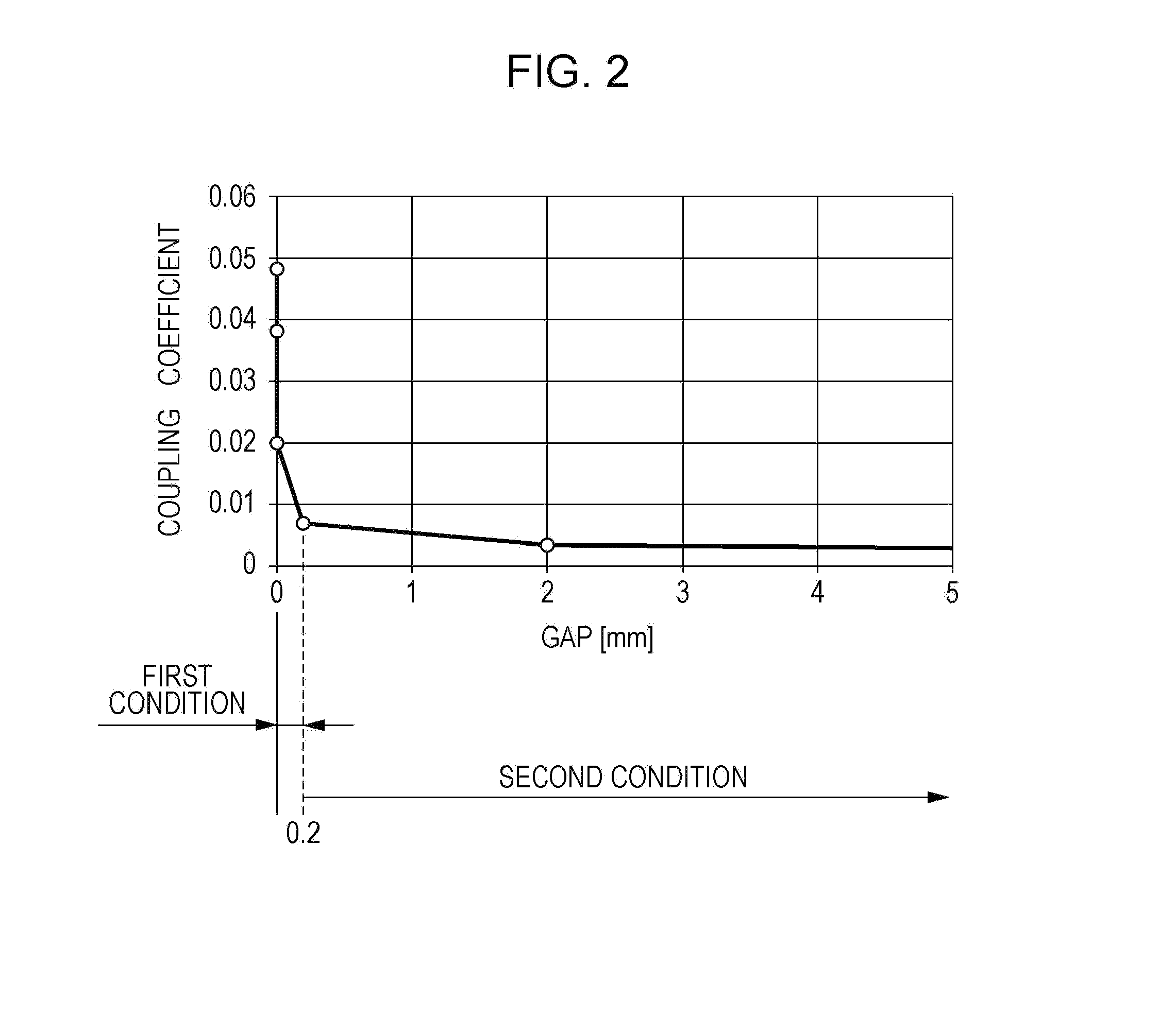
[0091]FIG. 2 is a graph showing a relationship between the coupling coefficient and a gap GP (see FIG. 1). The relationship between the coupling coefficient and the gap GP is described with reference to FIGS. 1 and 2.

[0092]The graph of FIG. 2 shows a result of electromagnetic field analysis using a finite element method. The horizontal axis of the graph of FIG. 2 represents the gap GP between the penetrating sections 311 and 321. The vertical axis of the graph of FIG. 2 represents the coupling coefficient between the first coil 210 and the second coil 220.

[0093]Under a first condition that the gap GP is not less than 0 mm and less than 0.2 mm, the coupling coefficient rapidly decreases as the gap GP increases. This m...

third embodiment

[0096]The designer may dispose an insulating member between two annular cores. The insulating member makes it hard for a magnetic flux to flow from one annular core to the other. This increases the power supply efficiency of a coil structure. In the Third Embodiment, the design principle of a coil structure including an insulating member is described.

[0097]FIG. 3 is a concept diagram of a coil structure 100A of the Third Embodiment. The coil structure 100A is described with reference to FIG. 3. Reference signs common to the First Embodiment and the Third Embodiment mean that elements given these reference signs have identical functions to those in the First Embodiment. Therefore, the description in the First Embodiment is applied to these elements.

[0098]As in the First Embodiment, the coil structure 100A includes a first coil 210, a second coil 220, a third coil 230, an annular first core 310, and an annular second core 320. The description of the First Embodiment is applied to thes...


PUM


Abstract

Disclosed is a coil structure including: a first coil that is a first primary coil; a second coil that is a second primary coil; a first core around which the first coil is wound, the first core having an annular shape; a second core around which the second coil is wound, the second core having an annular shape; and a third coil that is a secondary coil, the first core including a first penetrating section that penetrates the third coil, the second core including a second penetrating section that penetrates the third coil, the first penetrating section being separated from the second penetrating section.

Description

BACKGROUND[0001]1. Technical Field[0002]The present disclosure relates to a coil structure having a coil and a power source device in which the coil structure is incorporated.[0003]2. Description of the Related Art[0004]Various power electronics technologies have been developed for the purpose of reducing consumption of fossil fuels such as oil and coal. Power electronics technologies are applied, for example, to electric vehicles because high efficiency of conversion from electric energy to mechanical energy can be achieved by power electronics technologies. As a result of application of power electronics technologies to vehicles, the amount of carbon emission can be markedly reduced.[0005]A coil structure is utilized in the field of power electronics technologies. A transformer, which is one example of a coil structure, generally includes an input section connected to a circuit for input and an output section connected to a circuit for output. The output section is insulated from ...

Claims


Application Information

Patent Timeline
IPC IPC(8): H01F27/28H02M3/335H01F27/30H01F27/24H01F27/32
CPCH01F27/2895H01F27/24H02M3/33507H01F27/2823H01F27/306H01F27/32H01F3/10H01F27/38H02M7/493H02M3/33573
Inventor YAMAKAWA, TAKEHIKOKATO, AKIRASAKIYAMA, KAZUYUKI
Owner PANASONIC INTELLECTUAL PROPERTY MANAGEMENT CO LTD
Why Eureka
Try Eureka